


Installed
Correctly
Front
Rear
Right
Left
Rear
Fron
t
29
21
19
29
19
21
19
14
2
47
48
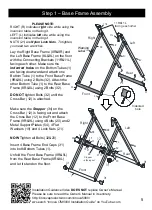
Before Installation, Please NOTE:
Connecting Brackets (11R&11L)
MUST
be pointing downward and the Pre-
Installed Backrest
MUST
be attached
from below and up into the connecting
brackets or the table will not invert
properly.
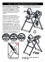
Step 3
– Pre-Installed Backrest to Base Frame
7
Installed Incorrectly
Connecting Brackets Must Point Downward
When Attaching the Pre-Installed Backrest
Attach the Pre-Installed Backrest
(2&47&48) to the Connecting Brackets
(11R&11L) using 4 Bolts (29), 4 Flat
Washers (19) and 4 Lock Nuts (21).
Screw the Angle Selector Pin (14) into
the Incline Position 15 hole and tighten.
11R
11L
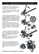
Low Position
Middle Position
High Position
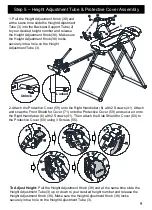
Headrest Adjustment:
To adjust the
Headrest (48), unscrew 2 Bolts (61) and
2 Flat Washers (51) and remove it from
the Backrest Support Tube (2). Move the
Headrest (48) to the position desired on
the Backrest Support Tube (2) and screw
2 Bolts (61) and 2 Flat Washers (51) to
secure the Headrest (48) into place.
TIGHTEN ALL NUTS AND BOLTS
AT THIS TIME.
2
48
61
48
61
2
48
2
61