


8R
6
22
19
20
19
21
19
19
8L
8R
22
6
Fro
nt
Rear
!
W
a
rn
in
g
L
a
b
e
l
21
19
20
8L
8R
7
26
19
Fron
t
Rear
!
W
a
rn
in
g
L
a
b
e
l
6
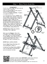
Step 2
– Handlebars Assembly
6
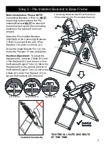
TIGHTEN ALL NUTS AND
BOLTS AT THIS TIME
Bolt 22 must
be installed
Warning
Label
1. Attach the Right Handlebar (6) to the
Rear Base Frame (8R) using 2 Bolts (20),
2 Flat Washers (19), and 2 Lock Nuts (21).
Be sure to insert Bolts (20) from the
inside of the frame. The Flat Washers
(19) and Lock Nuts (21) will be on the
outside of the frame.
DO NOT
tighten Bolts (20) until Bolt (22) is
installed. Use Bolt (22) and Flat Washer
(19) to secure the Right Handlebar (6) to
the Rear Base Frame (8R).
Tighten
Bolt (22) and Bolt (20) at this time.
2. Attach the Left Handlebar (7) to the
Rear Base Frame (8L) using 2 Bolts (20),
2 Flat Washers (19), and 2 Lock Nuts (21).
Unlock the chain that comes with the
Safety Pin (26) and secure the Safety Pin
(26) to the Right Handlebar (6) with the
chain provided. Insert the Safety Pin (26)
through the hole on the right side between
the 2 frames (8R&9R) to lock the Base
Frame open. See detailed picture.
Insert
Safety
Pin here
Secure
Chain
Here
6
26
CAUTION:
Bolt 22 must
be installed