Page 57
MAXIM Installation Instructions
© Mass Electronics Pty Ltd 2011
Appendix A – Using the CT01 Commissioning Tool
A-2.4 CT01 Menus and Navigation
The interface of the CT01 is relatively easy to navigate. To access the Menu page press the
Exit
button. To select how the CT01 is connected to the controller, select
Setup
and press the
Enter
button. Use the
Up
and
Down
navigation buttons to select between
Network
or
Standalone
. If the
CT01 is connected directly to a controller as illustrated in Figure A-1 preivously, you will need to select
Standalone
. If the CT01 is connected to the network as illustrated in Figure A-2 and Figure A-3, you
will need to select
Network
.
A-3 Logging onto the Controller
Connect the CT01 to the desired controller, or to the sub system network as described earlier, and the
screen should activate.
Press the
Log On
button.
Select the controller to communicate with and press the
Enter
button. If you are connected to a sub
system network, you will have a list of controllers on that network to choose from.
To navigate to the Watch Menu, select
Status
and press the
Enter
button. Now select
Watches
and
press the
Enter
button. You can now use the
Up
and
Down
navigation buttons to scroll through the
available selections. When indicated at the top of the LCD, you can press the
Enter
button to edit the
applicable set points. Pressing the
Exit
button will take you back to the previous menu or page. You
can view the following parameters in the Watch Menu:
• Zone temperature and temperature set point
• Cooling and heating demand
• Heater bank request
• Minimum and maximum air flow
• Airflow(L/S), air volume(m/3) and actual airflow set point
• Actuator travel time (only on DODC motors)
• Actuator demand
• Manual VAV calibration (for calibrating the pressure sensor and actuator position)
• Velocity Pressure (Pa)
• Pressure sensor fault status
• Commission mode enable, actuator manual enable, and actuator manual position.
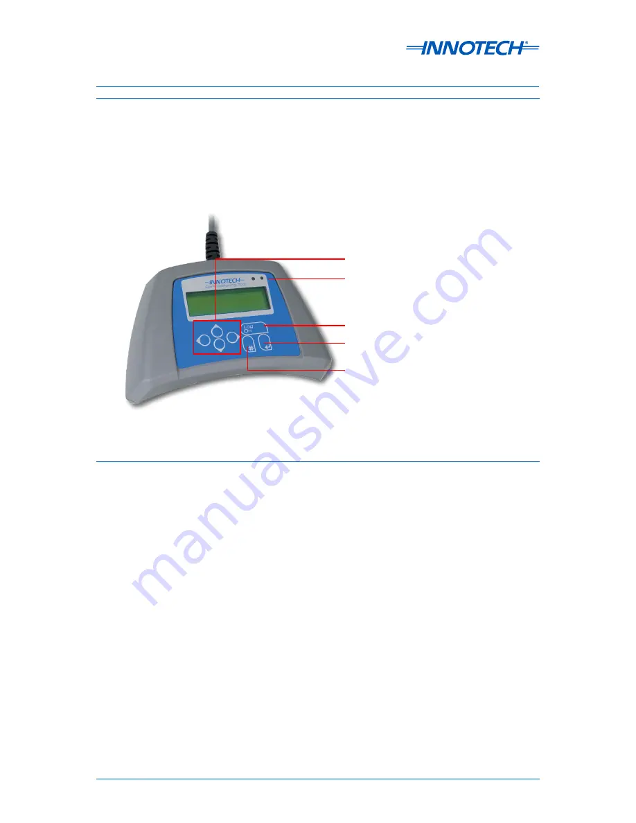
Figure A-4:
CT01 Interface - Navigation and Menus
Communication LEDs
Log On Button
Enter Button
Exit Button
Navigation Buttons
Summary of Contents for MAXIM 1010
Page 1: ...MAXIM Series Controllers INSTALLATION INSTRUCTIONS...
Page 9: ...Chapter 1 Preliminary Information MAXIM Series Controllers INSTALLATION INSTRUCTIONS...
Page 15: ...MAXIM Series Controllers INSTALLATION INSTRUCTIONS Chapter 2 Mechanical Installation...
Page 23: ...Chapter 3 Electrical Installation MAXIM Series Controllers INSTALLATION INSTRUCTIONS...
Page 41: ...Chapter 4 Network Installation MAXIM Series Controllers INSTALLATION INSTRUCTIONS...
Page 43: ...Chapter 5 Commissioning MAXIM Series Controllers INSTALLATION INSTRUCTIONS...


