background image

InnoMedia MTA8000 Series Administrative Guide  


Page 66


         Copyright © 2022 InnoMedia. All rights reserved.         

A

PPENDIX 

C:


W

I

F

C

ONNECTION 

S

ETUP THROUGH 

C

APTIVE 

P

ORTAL 


Connect the MTA to the Home Router through a WiFi connection.  You will connect the MTA to a WiFi Access 
Point using your smartphone, tablet or PC. Press the round button on the top of the unit for about 5 seconds, 

the MTA will switch to “Setup Mode” and the WiFi LED will ch

ange to solid yellow. Connect your smartphone 

or PC to the MTA’s preset SSID shown on the back of the unit, i.e., MTA8328

-xxxxxx, product name followed 

by the last 6 digits of MAC address. The MTA welcome portal web page will show up on your smartphone/PC. 
If this page does not popup, open a web browser and type in the following address: 
http://192.168.199.1/wifisetup/


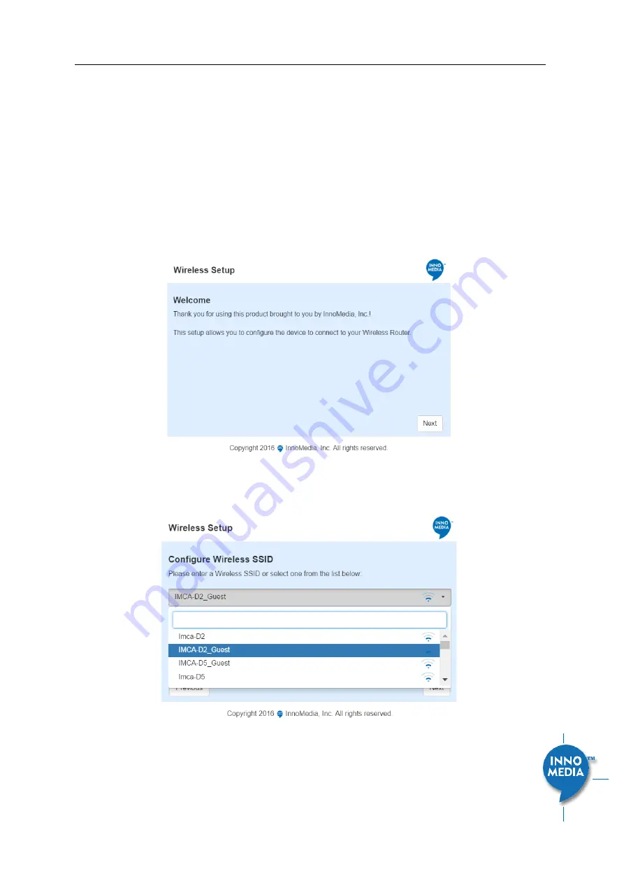
WiFi setup steps are as on the following screens:  

(1)


Welcome page 


Figure 55. Captive Portal - Welcome 

(2)


Select a Wireless SSID from the list, or just type the SSID name in the input box if the SSID name is 
hidden.  


Figure 56. Captive Portal 

 SSID selection 


Summary of Contents for MTA 8328-1N

Page 1: ...contains proprietary information of InnoMedia Inc and its receipt or possession does not convey any rights to reproduce disclose its contents or to manufacture use or sell anything it may describe It...

Page 2: ...2 DHCP Server Setting 16 3 1 3 Ethernet IP Address Setting 17 3 1 4 WiFi Configuration and IP Address Setting 18 3 1 5 LAN Interface IP Address Setting 18 3 1 6 Host and DNS Servers 18 3 1 7 Master D...

Page 3: ...ployed in the Field 51 5 7 EMS Setting 52 5 7 1 EMS Server 52 5 8 Trace Log 53 5 8 1 Trace Log Setting 53 5 9 System Time 55 5 9 1 Time Setting 55 5 10 Language 57 5 11 Uplink Connection 57 5 12 Certi...

Page 4: ...rver 16 Figure 11 Configuring the IP Address on the Ethernet Interface 17 Figure 12 WiFi Configuration and IP Address Setting 18 Figure 13 Configure the LAN IP address 18 Figure 14 Configuring the hos...

Page 5: ...e Permission Setting 47 Figure 42 Firmware Upload 47 Figure 43 Reboot Dialog 48 Figure 44 Restore To Factory Dialog 48 Figure 45 Provisioning Server Setting 49 Figure 46 Configuring EMS Server Informa...

Page 6: ...onfigurations required Revision History Date Version Notes 2016 10 25 V1 0 Based on firmware V1 0 0 19 2016 11 08 V1 1 Based on firmware V1 0 0 23 2016 11 23 V1 1 Based on firmware V1 0 0 27 2017 03 2...

Page 7: ...user is encouraged to try to correct the interference using one of the following measures Reorient or relocate the receiving antenna Increase the separation between the equipment and receiver Connect...

Page 8: ...t connection or through WiFi1 This guide will help you to quickly install and configure your unit so that you can start placing calls right away 1 2 Package Contents 1 2 1 Residential models MTA8328 1...

Page 9: ...ential Models Out of the Box Setup This section provides a step by step guide to install the MTA and setup the system for connecting to a broadband network Before starting the Installation make sure y...

Page 10: ...i passphrase For detailed instructions please see Appendix C WiFi Connection Setup through Captive Portal Confirm that the MTA is successfully connected to the Home Router and acquires an IP address a...

Page 11: ...the round button on the top of the MTA box Double click the round button on the top of the unit After the WCO test is complete the result is displayed through its respective LED state as shown in LED...

Page 12: ...on your router or LAN network switch Confirm that the MTA is successfully connected to the Router and acquires an IP address If the WAN LED shows steady green it is connected The MTA WAN interface is...

Page 13: ...e MTA WAN interface will be played through the telephone handset When the Ethernet WAN interface is connected to the Router the IP address played is always the Ethernet WAN IP otherwise the WiFi WAN I...

Page 14: ...P accounts provisioned Reg Status Successfully REGISTERED with SIP proxy Not REGISTERED with SIP proxy Account disabled State Phone on hook Phone off hook System Information MAC address of Ethernet WA...

Page 15: ...er of DNS servers in order of decreasing priority used is Master DNS server s those obtained from the DHCP server user configured DNS server s See section 3 1 7 for details on Master DNS Domain Name t...

Page 16: ...onfigure the Operation Mode Field Name Description Network Operation Mode Switch Mode the factory default setting The MTA LAN ports are switch ports Hosts connect to the LAN ports have the same IP net...

Page 17: ...lease time offered to the LAN hosts Static DNS 1 2 3 Input the DNS server s that the MTA offers to its LAN hosts 3 1 3Ethernet IP Address Setting Configure the IPv4 IP address for the device Click the...

Page 18: ...be retrieved from this page by the administrator if it is entered through the Captive Portal page 3 1 5LAN Interface IP Address Setting This page is applicable to the MTA8328 MP series models Configur...

Page 19: ...If Master DNS is configured the MTA gets related DNS services from this configured server to perform voice communication functions The MTA acquires DNS information from the following servers in the p...

Page 20: ...1 5 Figure 15 Configuring the Master DNS Information Field Name Description DNS Server Configure the DNS server information specified by the VoIP service provider for up to 3 DNS servers 3 1 8TOS Sett...

Page 21: ...InnoMedia MTA8000 Series Administrative Guide Page 21 Copyright 2022 InnoMedia All rights reserved Voice Traffic Use the configured TOS value to tag voice RTP packets...

Page 22: ...tings Feature and Service Code Settings Fax Settings and Call Report Settings which are described in the following sections Click on the Edit icon of a particular profile to display the profile settin...

Page 23: ...in SIP based networks that also provide layer 2 layer 3 connectivity through different access technologies SIP User Agents may use this header to relay information about the access technology to prox...

Page 24: ...r to the most preferred SIP server lowest priority in the SRV query response Disable rport Support Do not append rport response port number in the Via header Using SIP Notify for Flashhook Support Sen...

Page 25: ...nversation Accept resync check sync reboot When enabled the MTA device supports events triggered by SIP NOTIFY messages sent to the MTA from the SIP server Event types are 1 check sync MTA reboots its...

Page 26: ...t messages Reject with 400 The MTA replies with an error SIP response code of 400 to the sender Additional Trusted SIP Entities Input one or more addresses IP or FQDN for additional servers from which...

Page 27: ...Hz RTP timestamp clock rate Telephone Event 48000 for use with codecs operating at a 48000Hz RTP timestamp clock rate 4 1 4SIP Timer Setting SIP timers define transaction expiration timers retransmiss...

Page 28: ...r the max number of non INVITE retries has been attempted Register Expiration Time Time to wait after a registration before it expires Generic SIP version If the timer is set to be x seconds the MTA r...

Page 29: ...led and the digitmap the MTA device sends the digits to the server to initiate the call If there is no match the system waits for the user to enter more digits or press the send key to indicate dialin...

Page 30: ...mber Bailout Number The outgoing number when early bailout is enabled Second DialTone Number List Once the Secondary Dial Tone SDT prefix is matched the user hears the secondary dial tone Digits diale...

Page 31: ...SIP Device will attempt to find a shortest possible match Regardless of the above syntax a timer is currently only allowed if it appears in the last position in a string Each string in the list is an...

Page 32: ...versal Enable Polarity Reversal Tip and Ring are reversed when a call is answered Max Flash Hook Timer The maximum flash hook cannot last more than X ms for the MTA to treat it as a Flash Hook Min Fla...

Page 33: ...Setting Jitter Buffer Mode Adaptive Jitter Buffer Size changes during the call in response to network conditions Fixed Jitter Buffer Size stays at the programmed value NetEQ when NetEQ is selected th...

Page 34: ...l Transfer The service code to transfer the current call to another destination Caller ID Display The service code to display the incoming caller phone number and its display name Caller ID Block The...

Page 35: ...both approaches described above Consult your service provider for the appropriate configuration when needed Figure 26 Fax Setting Field Name Description Basic Setting Jitter Buffer Size A jitter buffe...

Page 36: ...etting Configure Call Detail report setting When a call terminates the MTA will generate and send the CDR details of the terminated phone call to a CDR server In addition the MTA can send RTCP XR repo...

Page 37: ...ld be used for this account User ID Account User ID Name Password Account Password Display Name Name to be displayed for Caller ID Authentication ID Authentication ID if needed 4 2 2Features Setting F...

Page 38: ...cts a third person to the current two way conversation Display Remote Caller ID Display of Caller ID the caller phone number and display name for inbound calls from a remote party Reject Anonymous Cal...

Page 39: ...of the parties involved in a call is not speaking Available options Negotiated Disabled Echo Cancellation Enable or disable line echo cancellation Secure RTP Two options are supported Disabled SDES th...

Page 40: ...NOTIFY messages which include AOR related information in XML format Enable MWI Subscribe The MTA subscribes to the Message Waiting Indicator event package as defined by 3GPP MWI Subscribe URI Specify...

Page 41: ...must be an even number Media Port End The highest RTP port number to be used when sending RTP RTCP traffic It must be an odd number 4 3 2 Regional Setting Figure 35 Regional settings for power and an...

Page 42: ...he MTA is ready to accept calls Busy Tone A busy signal indicates a failure to complete the requested call Reasons could be The called number is occupied or The other party has hung up at the end of a...

Page 43: ...nce settings control the timing of the incoming ring signal This varies from country to country and may consist for instance of the ring voltage being applied for two seconds followed by four seconds...

Page 44: ...uite of standards based electrical tests Click all the checkboxes for which GR909 confirmation is required Then Click the Start Test button NOTE If the Receiver is Off hook the REN Test and the Resist...

Page 45: ...ults Test This procedure measures TIP to RING on hook DC resistance A DC resistance less than 150 k is reported as a failure 4 4 2GR909 Tests triggered from SIP NOTIFY Message The MTA supports server...

Page 46: ...and Password Default ID is admin Default Password is password However the default values are service provider dependent 5 1 2End User Account Setting Figure 40 User Account Setting Field Name Descript...

Page 47: ...yright 2022 InnoMedia All rights reserved Figure 41 User Page Permission Setting Field Name Description User Page Permission Setting Configure which pages the User Login account can access 5 3 Firmwar...

Page 48: ...ystem firmware to be active 5 4 Reboot Figure 43 Reboot Dialog Field Name Description Reboot Reboot opens a dialog box and asks for a confirmation to Reboot the System 5 5 Restore To Factory Figure 44...

Page 49: ...l not need to manually configure the MTA with its SIP Profile and User Information since the desired information can be entered into the Configuration File for that unit Subsequently when the device i...

Page 50: ...User ID The User ID used for HTTP FTP and HTTPS authentication purposes Password The Password used for HTTP FTP and HTTPS authentication purposes Protocol The Protocol to connect to the server Suppor...

Page 51: ...e MTA triggers next provisioning immediately to the new server and or config file This setting can be used for instance to set up a provisioning server re direct whereby an initial provisioning server...

Page 52: ...This System Prov Restore2Default tag value transitions 0 to 1 further provisioning events will not trigger an RSTD event even if this tag is left as 1 A set of factory default files has been download...

Page 53: ...ed Heartbeat type The MTA will send a heartbeat to the EMS Server to let it know it is up and running A Data Tunnel between the EMS and MTA is used and this can be encrypted or not depending on the Op...

Page 54: ...Setting table Figure 47 Trace Log Setting Trace Log Setting Description Enable Trace Log Enables the trace log Trace Level Follows RFC5424 syslog message severities 1 Alert Action must be taken immedi...

Page 55: ...ver Syslog Server Syslog server IP address or FQDN Trace Group Setting Description Item list Select items to monitor and display associated messages These messages can be displayed on the CLI console...

Page 56: ...can be modified through the pull down list Note a reboot is needed for this setting to become effective Enable DST Enable or disable daylight saving time DST Start Month Week WeekDay Time Configure th...

Page 57: ...y as the peer updates and sets the local time 5 10 Language The MTA device supports English Spanish for Interactive Voice Response IVR services Select the desired language for your needs Figure 49 Lan...

Page 58: ...ication Key Field Name Description SIP CA Certificate Root certificate for verifying the SIP server TLS Certificate Prov CA Certificate Root certificate for verifying the Provisioning server Certifica...

Page 59: ...interface s SNMP Port The port for SNMP communications SNMP Manager IP address or FQDN of the SNMP Manager system Enable SNMP Trap Enable Disable sending traps to the SNMP server Refer to the associat...

Page 60: ...SSH and configure what port SSH will be allowed to use WEB WAN LAN Access Enable Disable WAN LAN access via HTTP or HTTPS and configure what ports will be used for each Enable Force Secure Web Access...

Page 61: ...ar enclosed in the square bracket to enter that particular section Type question mark at any level to display available commands Type cd to go back to the upper level f factory sub menu is password pr...

Page 62: ...Yellow WiFi has failed the setup or it is disconnected after a successful connection Medium Slow Blinking Yellow 1 sec on 1 sec off WiFi is in the process of being setup via the welcome portal Off WiF...

Page 63: ...linking Green 1 sec on 1 sec off Device firmware is being upgraded The PHONE LED blinks in unison with the WAN LED LAN Solid Green LAN Ethernet 100BT link is active blink with activities Solid Yellow...

Page 64: ...T link is active blinks with activity Medium Slow Blinking Yellow 1 sec on 1 sec off Device firmware is being upgraded The PHONE LED blinks in unison with all other LEDs except PWR LED Off LAN Etherne...

Page 65: ...s MTA_sample_config txt MTA Output Encrypted config file MTA001099001122 cfg is created Openssl command example Provisioning config file should be encrypted using the following command at the provisio...

Page 66: ...will change to solid yellow Connect your smartphone or PC to the MTA s preset SSID shown on the back of the unit i e MTA8328 xxxxxx product name followed by the last 6 digits of MAC address The MTA w...

Page 67: ...e 67 Copyright 2022 InnoMedia All rights reserved 3 Input the password for the selected SSID Figure 57 Captive Portal SSID password input 4 Complete the WiFi setup and start the voice quality validati...

Page 68: ...nd DHCP Option 67 together 1 This method requires the user to configure the MTA provisioning protocol and server port settings Protocol Choose among options HTTP HTTPS TFTP FTP Server Port The provisi...

Reviews: