14 | INSTRUCTION MANUAL INNO
PICCO
6.2 DRY WALL INSTALLATION
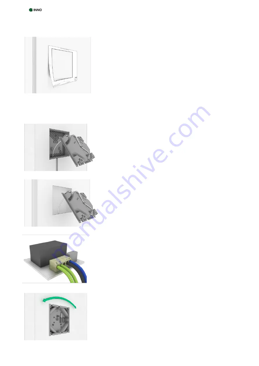
6.3 INSTALLING THE INSTALLATION BOX AND METAL FRAME
Figure 4
Figure 5
Figure 8
Figure 7
Figure 6
*Trademark notice: iPad™ and iPad Mini
TM
are trademarks of Apple Inc., registered in the U.S. and other countries
1. Remove the template for dry wall installation from the packaging, set it
up horizontally at the installation site, and trace the inner lines with a
pen (Fig. 4).
2. Ensure that the wall is free of supply pipes, cables and metal struts at the
installation site. Carefully remove the area within the markings so as to
insert the installation box.
1. Remove the transport lock then take the installation box out of its packa-
ging.
2. Hold the installation box to the flush-mounting box (Fig. 5) or for dry
wall installation to the wall opening (Fig. 6), taking care that the „TOP“
marking at the bottom of the box is facing up, and break out the cable
feedthrough.
3. Ensure that all live cables are disconnected from the power supply at the
installation site! Feed the power cable through the opening into the in-
stallation box. Take care not to damage the cables.
4. Secure the power cable to the rear of the installation box with the tensi-
on relief (Fig. 5 / Fig. 6). The tension relief can be adjusted for various ca-
ble diameters by rotating the tension relief lever.
5. All electrical installations must be carried out by a qualified electrician.
Cut the power cable to a suitable length and attach it to the pre-assem-
bled power supply unit in compliance with the connection regulations
(Fig. 7).
6. For solid wall installation insert the installation box in the flush-moun-
ting box, ensuring that the „TOP“ marking is facing up, and fix it with the
3 bolts. Adjust the installation box perpendicularly with the help of the
pendulum receptacle of the flush-mounting box and fix it in position by
tightening the 3 bolts (Fig. 8).
7. For dry wall installation insert the installation box in the wall opening
with the „TOP“ marking facing up and fix it perpendicularly by screwing
the 6 metal braces until you feel a resistance (Fig. 8). The 6 braces auto-
matically move outward when screwing, tightening against the inner
dry wall and thus fixing the installation box.
8. Take the metal support out of the packaging and ensure that all live
cables are disconnected from the power supply at the installation site!
All electrical installations must be carried out by a qualified electrician.
To earth the metal support, connect the earth cable to the earth connec-
tion on the rear of the metal support.


