DE
INSTRUCTION MANUAL INNO
PICCO
| 13
5 PREPARING FOR INSTALLATION
*Trademark notice: iPad™ and iPad Mini
TM
are trademarks of Apple Inc., registered in the U.S. and other countries.
Figure 1
Figure 2
Figure 3
6 INSTALLING THE INNO
PICCO
6.1 SOLID WALL INSTALLATION
5.1 CHOOSING THE INSTALLATION SITE
The following factors must be considered when choosing the installation site so as to ensure that the INNO
PICCO
can be easily
installed and the iPad™* / iPad Mini
TM
* can be operated without problems:
A sufficiently strong WiFi signal must be available in the area for the iPad™*/ iPad Mini
TM
* to operate correctly.
At the installation site, it must be possible to go 56 mm into a solid wall or 45 mm into a dry wall.
The installation site should not be exposed to direct sunlight and maintain temperatures between 0 °C and 35 °C and a
relative humidity between 10 % and 95 % (no condensation).
A sufficient power supply (according to specifications) has to be available at the installation site.
When installing the device in a solid wall, the area should be free of cables, supply pipes and supporting struts.
Installation height must be in an optimal position for all users.
We recommend using the flush-mounting box for perfectly fitting the
INNO
PICCO
into a solid wall. It is specially designed to accommodate the
installation box and guarantees that the complete INNO IN-WALL SYSTEM
SOLUTION is perfectly aligned and seated securely. This item is not included
in the scope of delivery but can be ordered separately (product number: INN
PAD-UP-99-99-02-00).
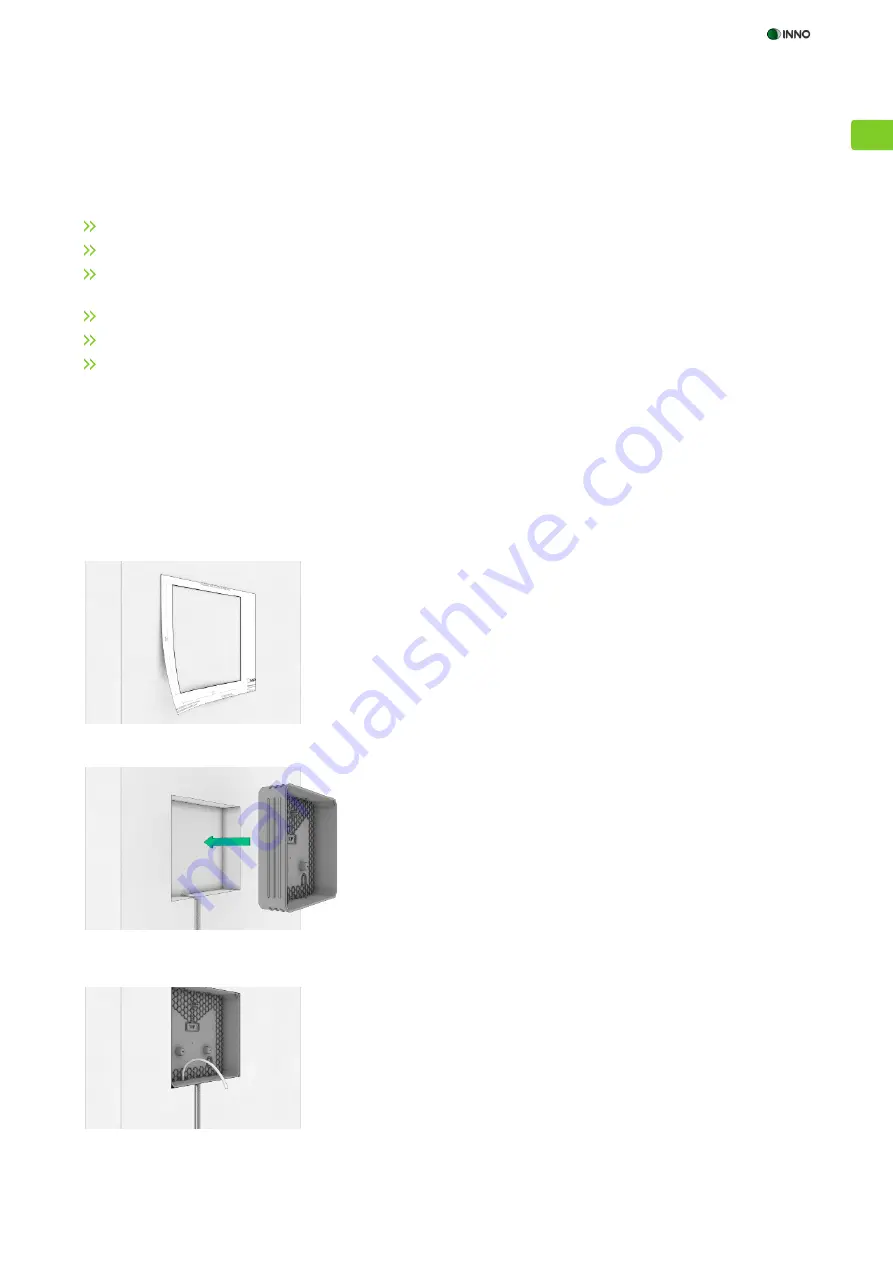
1. Take the template for solid wall installations from the packaging and set it
up horizontally at the installation site.
2. Fix the template to the wall with adhesive tape and trace the inner lines
with a pen (Fig. 1).
3. Ensure that the wall is free of supply pipes, cables and metal struts at the
installation site.
4. Carefully remove the area of wall within the markings so as to insert the
flush-mounting box.
5. Hold the flush-mounting box to the wall, taking care that the „TOP“ mar-
king at the bottom of the box is facing up, and find the optimal position
for feeding the power cable into the box (Fig. 2).
6. Ensure that all live cables are disconnected from the power supply at the
installation site! Break out the corresponding cable feedthrough and feed
the power cable through the opening into the flush-mounting box. Take
care not to damage the cables.
7. Insert the flush-mounting box perpendicularly into the wall recess, ensu-
ring that the „TOP“ marking is facing up, and fix the box to the wall
(Fig. 3). Use the fixing holes in the bottom of the flush-mounting box for
this purpose.
8. To fix the flush-mounting box in this position, plaster must be applied
around it so that it fits smoothly into the wall. Apply the plaster to all
sides of the box so that there are no protruding parts and wipe away all
excess plaster to provide a flush finish.


