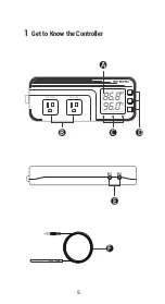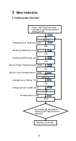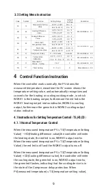
6
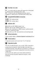
Functions on screen
PV
:
In normal mode, the measured temperature is displayed.
In settings mode, it will display menu code.
SV
:
In normal mode, the temperature setting value is
displayed. In setting mode, it will display the setting value.
Output(WORK1/WORK2) Instruction
WORK1:
The heating output
WORK2:
The cooling output
Indicator LED:
●
Red LED is on WORK1 output is on.
●
Green LED is on WORK2 output is on.
●
Green LED is blinking WORK2 output is performing the
function of compressor delay.
●
Yellow LED is on The controller is in the setting mode.
Button Instruction
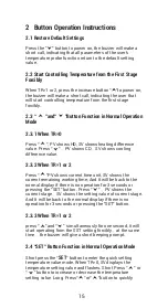
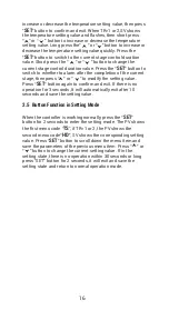
Please read the detail on
2.Button Operation Instructions
below.
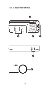
Probe interface
Temperature probe can be insert into P1 or P2 interface.
Temperature probe
If the controller display Er, you may get a false temperature
probe, please try harder to insert the probe and rotate it to
make good contact. If the problem is still persists, it is likely the
internal probe wire has been damaged by the moisture or heat
temperature.
The probe and cable cannot be touched by the flame.
Do not exceed the probe temperature range to avoid
damaging.
A
B
D
E
F
C
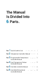
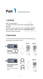
Summary of Contents for ITC-608T
Page 1: ...ITC 608T Manual...
Page 7: ...5 86 8f 96 0f WORK1 WORK2 A B C D E F P1 P2 1 Get to Know the Controller...
Page 15: ...13 86 8f 96 0f WORK1 WORK2 A B C D E F P1 P2 1 Get to Know the Controller...
Page 28: ...26 DUAL TEMPERATURE PROBES Controller Manual ITC 608T Part 4...
Page 29: ...27 WORK1 WORK2 A B C D E F P1 P2 1 Get to Know the Controller 88 6f 98 6f...
Page 38: ...36 HUMIDITY Controller Manual Equivalent to IHC 200 Humidity Controller Manual ITC 608T Part 5...
Page 39: ...37 56 8 66 0 WORK1 WORK2 A B C D E F P1 P2 1 Get to Know the Controller...
Page 46: ...44 WORK1 WORK2 A B C D E F P1 P2 1 Get to Know the Controller 88 6f 56 8...


