background image

15

2   Button Operation Instructions

2.1 Restore Default Settings

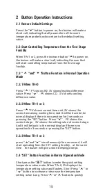
Press the "     " button to power on, the buzzer will make a 

short call, indicating that all parameters of the user's 

temperature probe function return to the default setting 

value.

2.2 Start Controlling Temperature from the First Stage 

Forcibly

When TR=1 or 2, press the increase button “    ”to power on, 

the buzzer will make a short call, indicating the user that 

will start controlling temperature from the first stage 

forcibly.

2.3 “        ”and“       ”Button Function in Normal Operation 

Mode

2.3.1 When TR=0

Press “      ”, PV shows HD, SV shows heating difference 

value. Press “      ”

PV shows CD

SV shows cooling 

difference value.

2.3.2 When TR=1 or 2

Press “      ”PV shows current time unit, SV shows the 

current remaining working time; And It will be back to the 

normal display if there is no operation for 3 seconds or 

pressing the "SET" button. Press “      ”

PV shows the 

current stage

SV shows the setting value of current stage. 

And It will be back to the normal display if there is no 

operation for 3 seconds or pressing the "SET" button.

2.3.3 When TR=1 or 2

press “      ”and“      ”  simultaneously for one second, it will 

start operating from the SST setting forcibly

at the same 

time

 the buzzer will give a short beeping prompt.

2.4 “SET” Button Function in Normal Operation Mode

Short press the “

SET

” button to enter the quick setting 

temperature value mode. When TR=0, SV displays the 

temperature setting value and flashes. Short Press “      ” or 

“      ” button to increase or decrease the temperature 

setting value. Long  Press“      ”or“      ”button to quickly 

Summary of Contents for ITC-608T

Page 1: ...ITC 608T Manual...

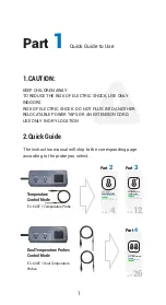
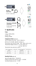
Page 2: ...d Into 6 Parts Part 2 Temperature Controller Manual Part 3 Programmable Temperature Controller Manual Part 5 Humidity Controller Manual Part 6 Humidity Temperature Controller Manual 1 4 12 36 Part 4 D...

Page 3: ...ture Controller Manual PROGRAMMABLE TEMPERATURE Controller Manual Equivalent to ITC 310T B Temperature Controller Manual ITC 608T ITC 608T Temperature Control Mode ITC 608T Temperature Probe 2 Quick G...

Page 4: ...ahrenheit Fahrenheit Error 40 T 10 2 40 T 50 3 10 T 80 1 50 T 176 2 80 T 100 2 176 T 212 3 Humidity Probe optional Type of humidity probe HTG3515CH Relative humidity measurement range 5 99 RH Humidity...

Page 5: ...year from the date of purchase when operated under normal condition by the original purchaser not transferable against defects caused by INKBIRD s workmanship or materials This warranty is limited to...

Page 6: ...4 TEMPERATURE Controller Manual Equivalent to ITC 308 Temperature Controller Manual ITC 608T Part 2...

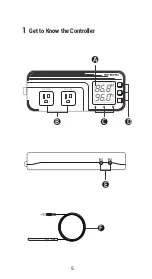
Page 7: ...5 86 8f 96 0f WORK1 WORK2 A B C D E F P1 P2 1 Get to Know the Controller...

Page 8: ...he function of compressor delay Yellow LED is on The controller is in the setting mode Button Instruction Please read the detail on 2 Button Operation Instructionsbelow Probe interface Temperature pro...

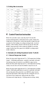
Page 9: ...value and flashes and short press or button to increase or decrease the setting value long press or button to quickly increase or decrease the setting value nally press the SET button again to con rm...

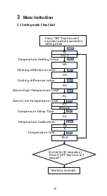
Page 10: ...rm High Temperature Limit Alarm Low Temperature Limit Compressor Delay Time Temperature Calibration Temperature Unit Press SET Key forover2 seconds to enterparameters setting mode TS 77 0 HD CD AH AL...

Page 11: ...ature setting value and automatically recognizes and converts for the heating or cooling working mode in which WORK1 is the heating output furthermore the red led is the WORK1 heating output status in...

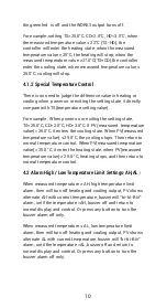
Page 12: ...ate When PV measured temperature value 25 0 C the cooling stops Then return to normal temperature control When PV measured temperature value 25 0 C it enter the heating state when PV measured temperat...

Page 13: ...on CA When the measured temperature deviates from the standard temperature the temperature calibration function can be used to make the measured value of the instrument consistent with the standard va...

Page 14: ...12 PROGRAMMABLE TEMPERATURE Controller Manual Equivalent to ITC 310T B Temperature Controller Manual ITC 608T Part 3...

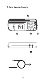
Page 15: ...13 86 8f 96 0f WORK1 WORK2 A B C D E F P1 P2 1 Get to Know the Controller...

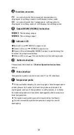
Page 16: ...he function of compressor delay Yellow LED is on The controller is in the setting mode Button Instruction Please read the detail on 2 Button Operation Instructions below Probe interface Temperature pr...

Page 17: ...TR 1 or 2 Press PV shows current time unit SV shows the current remaining working time And It will be back to the normal display if there is no operation for 3 seconds or pressing the SET button Press...

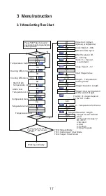
Page 18: ...press or to modify the setting value Press SET button again to con rm and exit If there is no operation for 3 seconds It will automatically exit after 10 seconds and save the setting value 2 5 Button...

Page 19: ...Qty of stages depend on the STT Value Compressor Delay Time Stage12 Temperature Set Value Temperature Calibration Stage12 Duration Length Temperature Unit Stage12 User De ned Alert at the end of stag...

Page 20: ...ture Setting Value 25 0 or 77 0 H03 H03 Stage 3 Control Duration Value 10 U03 U03 Whether to Alarm after the Completion of Stage 3 n S04 S04 Stage 4 Temperature Setting Value 25 0 or 77 0 H04 H04 Stag...

Page 21: ...eating or cooling working mode in which WORK1 is the heating output furthermore the red led is the WORK1 heating output status indicator WORK2 is cooling output furthermore the green led is WORK2 cool...

Page 22: ...to normal temperature control When PV measured temperature value 25 0 C it enter the heating state when PV measured temperature value 25 0 C heating stops and then return to normal temperature contro...

Page 23: ...to make the measured value of the instrument consistent with the standard value The calibrated temperature the measured temperature the calibration value 4 5 Fahrenheit or Celsius Settings CF The use...

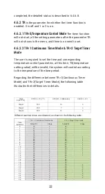
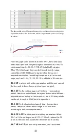
Page 24: ...he temperature of the time period Regarding the difference between TR 1 Continuous Timer Mode and TR 2 Target Timer Mode the following table illustrates their differences in details Stage X N 1 12 STX...

Page 25: ...the stage control time H01 H03 is only started when the current temperature reaches the setting temperature of the current stage such as 5 14 19 25 32 35 and total is 39 minutes 4 6 3 UT is a time un...

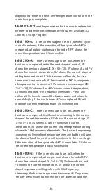
Page 26: ...ately Press any button at this time to cancel the buzzer alarm and return to normal display If the cycle index MD is completed PV will show the current temperature and SV will show End 4 6 8 3 UX C If...

Page 27: ...AT 1 Automatic Mode after the power is turned off the time still counts After the power is turned on again when TR 1 and UX X 01 12 is n or A the temperature controller will automatically calculate t...

Page 28: ...26 DUAL TEMPERATURE PROBES Controller Manual ITC 608T Part 4...

Page 29: ...27 WORK1 WORK2 A B C D E F P1 P2 1 Get to Know the Controller 88 6f 98 6f...

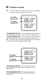
Page 30: ...mode the indicator LED is on otherwise off SV In normal mode the P2 measured temperature is displayed In setting mode it will display the setting value P2 Heating indicator LED If P2 Temperature Cont...

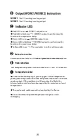
Page 31: ...s in the setting mode Button Instruction Please read the detail on 2 Button Operation Instructionsbelow Probe interface Two temperature probes can be insert into P1 and P2 interface Temperature probe...

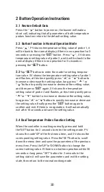
Page 32: ...rease or decrease the setting value and then press SET again SV shows the temperature setting value of probe 2 and flashes at this time quickly press or button to increase or decrease the setting valu...

Page 33: ...77 0 DS1 3 0 AH1 212 AH1 212 Heating or Cooling difference value STE Alarm High Temperature Limit STE Alarm Low Temperature Limit STE PT1 0Minute Working normally Compressor Delay Time STE CA1 0 0 Te...

Page 34: ...9 9 9 9 15 0 15 0 100 212 40 0 40 0 0 minute 0 0 0 0 25 0 77 0 2 0 100 212 40 0 40 0 40 0 100 40 0 212 0 3 15 0 40 0 100 40 0 212 40 0 100 40 0 212 0 10minute 9 9 9 9 15 0 15 0 25 0 77 0 2 0 F H 3 0...

Page 35: ...of Probe 2 When HC2 H the temperature mode is heating mode SV LED1 is on and when the measured temperature temperature setting value TS2 difference value DS2 it enters the heating state the WORK2 ind...

Page 36: ...ternate AL2 with current temperature buzzer will bi bi Biii alarm until the tempera ture AL2 buzzer off and return to normal display and control Or press any button to turn the buzzer alarm off only 5...

Page 37: ...heit or Celsius according to their habits The default temperature is Fahrenheit If you need to display the unit in Celsius then set the CF to C Please note that when the CF changes state all setting v...

Page 38: ...36 HUMIDITY Controller Manual Equivalent to IHC 200 Humidity Controller Manual ITC 608T Part 5...

Page 39: ...37 56 8 66 0 WORK1 WORK2 A B C D E F P1 P2 1 Get to Know the Controller...

Page 40: ...ng the function of compressor delay Yellow LED is on The controller is in the setting mode Button Instruction Please read the detail on 2 Button Operation Instructions below Probe interface Humidity p...

Page 41: ...ty value and flashes and short press or button to increase or decrease the setting value long press or button to quickly increase or decrease the setting value and press the SET button again to con rm...

Page 42: ...larm High humidity Limit SET Alarm Low humidity Limit Compressor Delay Time Humidity Calibration Press SET Key forover2 seconds to enterparameters setting mode HD 5 0 RH DD 5 0 RH AH 99 0 RH AL 5 0 RH...

Page 43: ...humidi ca tion output status indicator WORK2 is dehumidi cation output furthermore the green led is WORK2 dehumidi cation output status indicator When PV measured humidity HS humidity setting value HD...

Page 44: ...3 Dehumidifying Delay Protection Time PT In the dehumidifying mode when the power is turned on for the rst time it will not start dehumidi cation immediately when PV measured humidity value HS humidit...

Page 45: ...TEMPERATURE HUMIDITY Controller Manual Equivalent to IHC 230 Temperature Humidity Controller Manual ITC 608T 43 Part 6...

Page 46: ...44 WORK1 WORK2 A B C D E F P1 P2 1 Get to Know the Controller 88 6f 56 8...

Page 47: ...e indicator LED is on otherwise off SV In normal mode the measured humidity is displayed In setting mode it will display the setting value Humidi cation indicator LED If humidity Control Function sele...

Page 48: ...nstruction Please read the detail on 2 Button Operation Instructions below Probe interface Temperature or humidity probe can be insert into P1 or P2 Temperature humidity probe If the controller displa...

Page 49: ...ckly increase or decrease the setting value Short press the SET button again SV shows the current humidity setting value and flashes and short press or button to increase or decrease the setting value...

Page 50: ...AH AL PT 0Minute CA SET SET SET SET SET SET SET HC H No Key for 30 seconds or Presss SET key for over2 second Working normally T HS 50 0 RH DS 5 0 RH AH 99 0 RH AL 5 0 RH PT 0Minute CA 0 0 RH SET SET...

Page 51: ...dicator LED to indicate whether the user has chosen humidi cation or dehumidi cation The WORK1 is output control of Temperature furthermore the red led is the WORK1 output status indicator the WORK2 i...

Page 52: ...off and return to normal display and control Or press the button to turn the buzzer alarm off only When measured temperature AL low temperature limit alarm PV shows alternate AL with current temperatu...

Page 53: ...are less than the delay time it needs to operate the remaining delay time to start dehumidi cation Delay time will start counting from the WORK2 output off 4 6 Temperature and Humidity Calibration CA...

Page 54: ...Inkbird Tech C L support ink bird com www ink bird com 86 755 25738050 Shenzhen GD 518000 China...

Reviews: