19
U09
U09
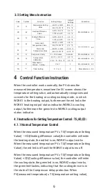
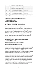
Whether to Alarm after the Completion of Stage
9
n
***
S10
S10
Stage 10 Temperature Setting Value
25.0
℃
or 77.0
℉
*
H10
H10
Stage 10 Control Duration Value
10
**
U10
U10
Whether to Alarm after the Completion of Stage
10
n
***
S11
S11
Stage 11 Temperature Setting Value
25.0
℃
or 77.0
℉
*
H11
H11
Stage 11 Control Duration Value
10
**
U11
U11
Whether to Alarm after the Completion of Stage
11
n
***
S12
S12
Stage 12 Temperature Setting Value
25.0
℃
or 77.0
℉
*
H12
H12
Stage 12 Control Duration Value
10
**
U12
U12
Whether to Alarm after the Completion of Stage
12
n
***
* The setting value range is the same as TS
** More details on 4.6.7
*** More details on 4.6.8
4. Control Function Instruction
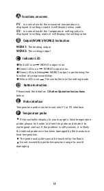
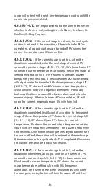
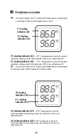
When the controller works normally, the PV shows the
measured temperature, meantime the SV screen shows the
temperature setting value, and automatically recognizes and
converts for the heating or cooling working mode , in which
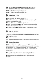
WORK1 is the heating output, furthermore the red led is the
WORK1 heating output status indicator;WORK2 is cooling
output, furthermore the green led is WORK2 cooling output
status indicator.
4.1 Instructions for Setting Temperature Control
(
TS,HD,CD,S01~S12
)
4.1.1 TR=0, Temperature Control Mode
4.1.1.1 Normal Temperature Control
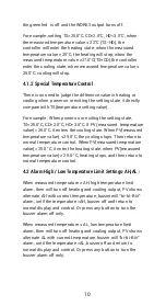
When the measured temperature PV ≤ TS(Temperature Setting
Value) – HD(Heating difference value),the controller will enter
the heating state, the red led is on, WORK1 output works.
When the measured temperature PV ≥ TS(Temperature Setting
Value), the red led is off and the WORK1 output turns off.
When the measured temperature PV ≥ TS(Temperature Setting
Value) + CD(Cooling difference value), the controller will enter
the cooling state, the green led is on, WORK2 output works;
the green led flashes, indicating that the cooling device is in
the state of the compressor delay protection. When
PV(measured temperature) ≤ TS(temperature setting value),
the green led is off and the WORK2 output turns off.
Summary of Contents for ITC-608T
Page 1: ...ITC 608T Manual...
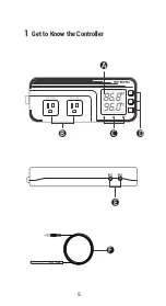
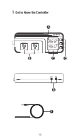
Page 7: ...5 86 8f 96 0f WORK1 WORK2 A B C D E F P1 P2 1 Get to Know the Controller...
Page 15: ...13 86 8f 96 0f WORK1 WORK2 A B C D E F P1 P2 1 Get to Know the Controller...
Page 28: ...26 DUAL TEMPERATURE PROBES Controller Manual ITC 608T Part 4...
Page 29: ...27 WORK1 WORK2 A B C D E F P1 P2 1 Get to Know the Controller 88 6f 98 6f...
Page 38: ...36 HUMIDITY Controller Manual Equivalent to IHC 200 Humidity Controller Manual ITC 608T Part 5...
Page 39: ...37 56 8 66 0 WORK1 WORK2 A B C D E F P1 P2 1 Get to Know the Controller...
Page 46: ...44 WORK1 WORK2 A B C D E F P1 P2 1 Get to Know the Controller 88 6f 56 8...

