SS-SVX10H-EN
13
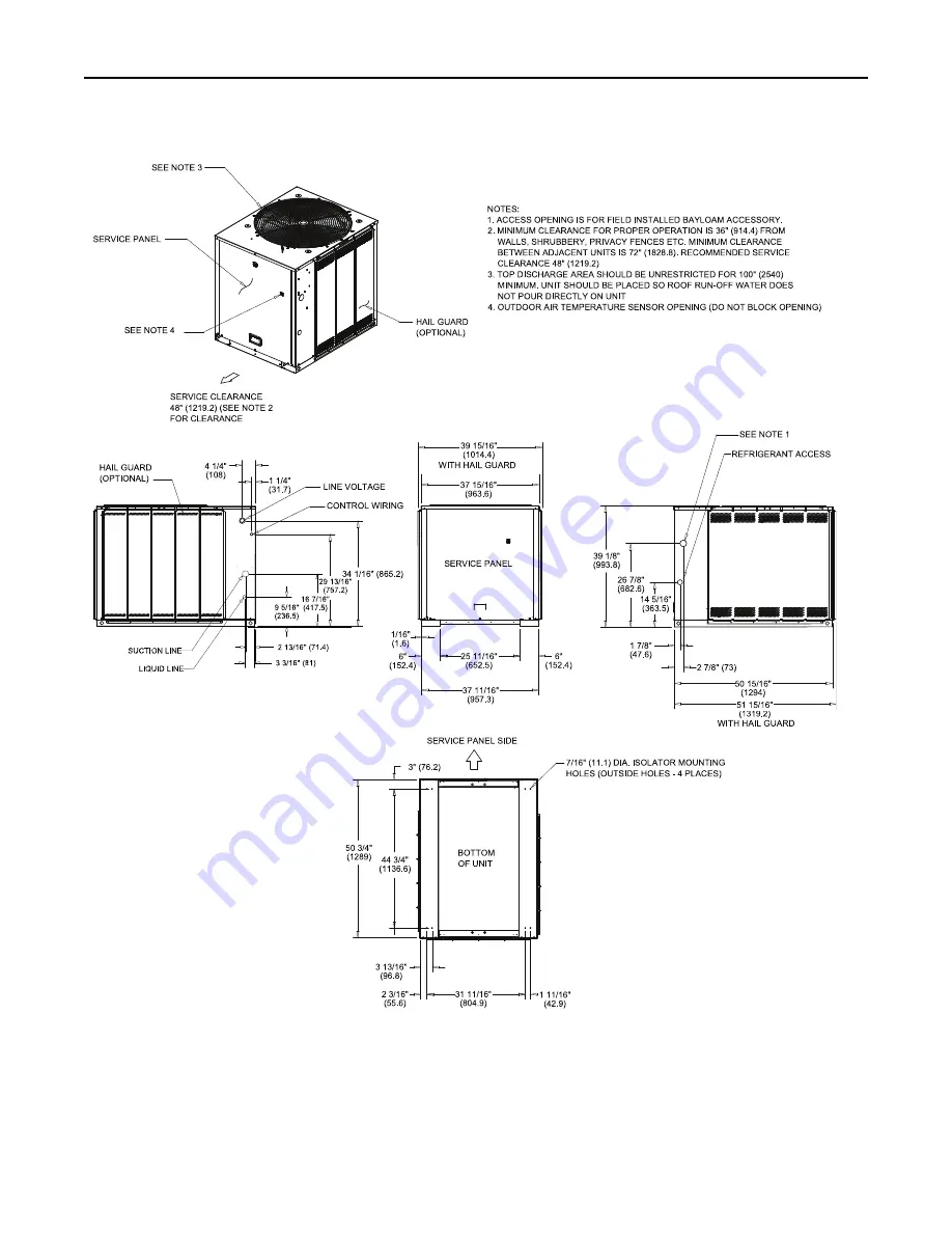
Figure 5.
8.33 and 10 ton condensing unit, single and manifolded compressor. microchannel
D
Diim
me
en
ns
siio
on
na
all D
Da
atta
a
Page 1: ...ualified person could result in death or serious injury When working on the equipment observe all precautions in the literature and on the tags stickers and labels that are attached to the equipment S...
Page 2: ...ta ak ke en n c co ou ul ld d r re es su ul lt t i in n d de ea at th h o or r s se er ri io ou us s i in nj ju ur ry y T Te ec ch hn ni ic ci ia an ns s i in n o or rd de er r t to o p pr ro ot te e...
Page 3: ...2 22 2 U Us se e O ON NL LY Y R R 4 41 10 0A A r ra at te ed d s se er rv vi ic ce e e eq qu ui ip pm me en nt t o or r c co om mp po on ne en nt ts s w wi it th h t th he es se e u un ni it ts s F F...
Page 4: ...Piping 42 Electrical Wiring 42 Pre Start 43 Control Circuit Features 43 Discharge Temperature Limit DTL 43 Low Outdoor Ambient Cooling 43 Evaporator Defrost Control EDC 43 Low Pressure Cut Out LPCO 43...
Page 5: ...Zone Temperature Sensor ZTS Service Indicator 50 Maintenance 51 Monthly 51 Annually Cooling Season 51 Coil Cleaning 51 Microchannel MCHE Coils 51 Maintenance Log 53 Wiring Diagram Matrix 54 T Ta ab b...
Page 6: ...ngle Circuit Microchannel H Dual Compressor Dual Circuit Microchannel J Dual Compressor Single Circuit Manifold Scroll Compressors Microchannel D DI IG GI IT T 8 8 E El le ec ct tr ri ic ca al l C Ch...
Page 7: ...nual Do not destroy or remove the manual from the unit The manual should remain weather protected with the unit until all installation procedures are complete N No ot te e It is not the intention of t...
Page 8: ...d d e eq qu ui ip pm me en nt t o or r p pr ro op pe er rt ty y o on nl ly y d da am ma ag ge e T Te es st t l li if ft t u un ni it t a ap pp pr ro ox xi im ma at te el ly y 2 24 4 i in nc ch he es s...
Page 9: ...oo of ft to op p i is s n no ot t p pr ro ot te ec ct te ed d d da am ma ag ge e t to o t th he e r ro oo of f m ma ay y o oc cc cu ur r I Im mp po or rt ta an nt t Refer to local building codes for p...
Page 10: ...n mm W in mm D in mm TTA061 073 076 090 46 1 1171 45 1143 38 965 2 TTA101 120 46 1 1171 55 1397 42 1067 TTA126 150 52 1 1323 55 1397 42 1067 TTA156 180 201 240 52 1 1323 96 2438 48 1219 TTA251 300 58...
Page 11: ...SS SVX10H EN 11 Figure 3 5 6 6 25 and 7 5 ton condensing unit single compressor microchannel D Di im me en ns si io on na al l D Da at ta a...
Page 12: ...12 SS SVX10H EN Figure 4 5 6 6 25 and 7 5 ton condensing unit dual compressor microchannel D Di im me en ns si io on na al l D Da at ta a...
Page 13: ...SS SVX10H EN 13 Figure 5 8 33 and 10 ton condensing unit single and manifolded compressor microchannel D Di im me en ns si io on na al l D Da at ta a...
Page 14: ...14 SS SVX10H EN Figure 6 8 33 and 10 ton condensing unit dual compressor microchannel D Di im me en ns si io on na al l D Da at ta a...
Page 15: ...SS SVX10H EN 15 Figure 7 10 4 and 12 5 ton condensing unit dual compressor microchannel D Di im me en ns si io on na al l D Da at ta a...
Page 16: ...16 SS SVX10H EN Figure 8 13 15 16 7 and 20 ton condensing unit dual compressor microchannel D Di im me en ns si io on na al l D Da at ta a...
Page 17: ...SS SVX10H EN 17 Figure 9 13 15 16 7 and 20 condensing unit manifolded compressor microchannel D Di im me en ns si io on na al l D Da at ta a...
Page 18: ...18 SS SVX10H EN Figure 10 20 9 and 25 ton condensing unit manifolded compressor microchannel D Di im me en ns si io on na al l D Da at ta a...
Page 19: ...80J 750 648 195 226 120 106 20 TTA240H 904 762 239 218 149 156 TTA240J 904 762 239 218 149 156 25 TTA300J 969 857 288 241 216 111 Table 2 TTA unit and corner weights lbs 50 Hz Tons Model No Shipping M...
Page 20: ...20 SS SVX10H EN Figure 11 TTA073 090 120 150 TTA061 076 101 Figure 12 TTA180 240 300 TTA156 201 251 W We ei ig gh ht ts s...
Page 21: ...g Guidelines Figure 13 Allowable elevation difference TTA above indoor unit Figure 14 Allowable elevation difference TTA or TWA below indoor unit N No ot te e Route refrigerant piping for minimum line...
Page 22: ...OT TI IC CE E S Sy ys st te em m C Co om mp po on ne en nt t D Da am ma ag ge e D Do o n no ot t r re em mo ov ve e t th he e s se ea al l c ca ap ps s f fr ro om m r re ef fr ri ig ge er ra an nt t c...
Page 23: ...liquid line gauge port 3 Braze the liquid line connections 4 Open the gauge port on the suction line and then braze the suction line to the connection stub Nitrogen will bleed out the open gauge port...
Page 24: ...3 Prior to starting a unit it is advisable to have the approved oils available in the event oil needs to be added to the system N NO OT TI IC CE E E Eq qu ui ip pm me en nt t D Da am ma ag ge e T Th h...
Page 25: ...2 1 375 1 3 8 TTA090H w TWE090E 7 25 7 3125 0 5 1 2 1 125 1 1 8 TTA101G w TWE101D 13 6 N A 0 5 1 2 1 375 1 3 8 TTA101H w TWE101E 7 7 7 6 0 5 1 2 1 125 1 1 8 TTA101J w TWE101D 13 1 N A 0 5 1 2 1 375 1...
Page 26: ...than 25 please refer to the Application Guide SS APG008 EN for charge levels and line sizes 2 See Figure 17 p 26 and Figure 18 p 27 for transition tube location and electrical connections 3 For additi...
Page 27: ...unit I Im mp po or rt ta an nt t If the unit is charged and left without power until a later date the crankcase heater should be energized for a minimum of 8 hours prior to powering the compressor s W...
Page 28: ...M MU US ST T b be e p pe er rf fo or rm me ed d b by y q qu ua al li if fi ie ed d p pe er rs so on nn ne el l I Im mp pr ro op pe er rl ly y i in ns st ta al ll le ed d a an nd d g gr ro ou un nd de...
Page 29: ...aTel jobsite connections A 3 power wires line voltage for 3 phase 2 power wires for single phase B 3 power wires line voltage for 3 phase 2 power wires for single phase C Cooling only thermostat 3 to...
Page 30: ...30 SS SVX10H EN Figure 22 Zone sensor field wiring Figure 23 Thermostat field wiring I In ns st ta al ll la at ti io on n...
Page 31: ...SS SVX10H EN 31 Figure 24 Thermostat wiring for electromechanical units I In ns st ta al ll la at ti io on n...
Page 32: ...32 SS SVX10H EN Refrigerant Circuit Figure 25 Typical split system cooling refrigerant circuit microchannel I In ns st ta al ll la at ti io on n...
Page 33: ...230 3 33 267 1 208 230 1 5 14 4 TTA120G4 1 460 3 17 142 1 460 1 2 5 5 8 TTA120GK 1 380 3 25 160 1 380 1 3 4 7 8 TTA120GW 1 575 3 16 80 1 575 1 2 5 1 10 TTA120H3 2 208 230 3 17 8 110 1 208 230 1 5 14...
Page 34: ...ts 60 Hz Tons Unit Model Number Unit Operating Voltage Range Minimum Circuit Ampacity Maximum Fuse or HACR Circuit Breaker Size 6 TTA073G3 187 253 30 5 50 TTA073G4 414 506 13 20 TTA073GK 342 418 15 20...
Page 35: ...Table 7 Electrical characteristics compressor and condenser fan motors 50 Hz Tons Unit Model Number Compressor Motor Condenser Fan Motor No Volts Phase Amps No Volts Phase Amps RLA Ea LRA Ea RLA Ea L...
Page 36: ...20 TTA061HD 380 415 14 15 6 25 TTA076GD 380 415 17 3 25 TTA076HD 380 415 16 7 20 8 33 TTA101GD 380 415 25 7 40 TTA101HD 380 415 19 9 25 TTA101JD 380 415 20 25 10 4 TTA126HD 380 415 26 35 13 TTA156HD...
Page 37: ...SS SVX10H EN 37 Charging Charts and Superheat Figure 26 TTA061G Figure 27 TTA061H Figure 28 TTA073G Figure 29 TTA073H Figure 30 TTA076G Figure 31 TTA076H...
Page 38: ...e 32 TTA090G Figure 33 TTA090H Figure 34 TTA101J Figure 35 TTA101G Figure 36 TTA101H Figure 37 TTA120G Figure 38 TTA120J Figure 39 TTA120H C Ch ha ar rg gi in ng g C Ch ha ar rt ts s a an nd d S Su up...
Page 39: ...SVX10H EN 39 Figure 40 TTA126H Figure 41 TTA150H Figure 42 TTA156H Figure 43 TTA156J Figure 44 TTA180H Figure 45 TTA180J C Ch ha ar rg gi in ng g C Ch ha ar rt ts s a an nd d S Su up pe er rh he ea at...
Page 40: ...TTA300J Table 9 TTA superheat with matched TWE air handler Condenser Air Handler Cooling Superheat Circuit 1 Circuit 2 TTA061G TWE076D 13 2 TTA061H TWE073E 14 7 15 6 TTA073G TWE090D 13 2 TTA073H TWE07...
Page 41: ...TA251J TWE251E 12 9 TTA300J TWE300E 12 9 Notes 1 An adjustable TXV is provided for each circuit in the TWE and TWA models If the application causes the superheat to deviate from the values shown above...
Page 42: ...n boards on microchannel units Refrigerant Piping Properly sized constructed liquid and suction lines connected to stubs at both the indoor and outdoor units Insulated the entire suction line Insulate...
Page 43: ...on pressure drops below the Low Pressure Cut Out setting Once the suction pressure has returned to normal the compressor and outdoor fans will cycle back on High Pressure Cut Out HPCO This control s s...
Page 44: ...the compressor contactor energizes on a call for cooling When the contacts of the compressor contactor close operation of the compressor and condenser fan begins The evaporator fan contactor also ene...
Page 45: ...units and 80 seconds on single compressor units after the cooling requirement has been satisfied to enhance unit efficiency When the heating cycle is terminated the evaporator fan relay coil is de ene...
Page 46: ...thod allows the technician to cycle a component O On n and have up to one hour to complete the check Service Test Mode will be ignored if a short is present across Test 1 and Test 2 at start up Resist...
Page 47: ...e following System status Heating status Cooling status N No ot te e If a System failure is indicated proceed to Step 4 If no failures are indicated proceed to Step 5 4 If a System failure is indicate...
Page 48: ...atus is done by checking voltage readings at the RTRM J6 The system indication descriptions and the approximate voltages are listed below System Failure Measure the voltage between terminals J6 9 J6 6...
Page 49: ...ju ur ry y W Wh he en n i it t i is s n ne ec ce es ss sa ar ry y t to o w wo or rk k w wi it th h l li iv ve e e el le ec ct tr ri ic ca al l c co om mp po on ne en nt ts s h ha av ve e a a q qu ua a...
Page 50: ...runs continuously the ZSM is good If you are not able to turn the fan on the ZSM is defective RLCI Loss of Communications If the RLCI loses input from the building management system the RTRM will con...
Page 51: ...he wiring insulation is intact Inspect the condenser coils for dirt and debris If the coils appear dirty clean them With the unit operating in the cooling mode check the suction and discharge pressure...
Page 52: ...e and an ECU of at least 180 with pressure no greater than 600 psi To minimize the risk of coil damage approach the cleaning of the coil with the pressure washer aimed perpendicular to the face of the...
Page 53: ...Superheat F at compressor Subcooling F at service valve Dry Bulb Wet Bulb Suction Pressure Discharge Pressure Circuit 1 Circuit 2 Circuit 1 Circuit 2 C1 C2 C1 C2 Note Perform each inspection once per...
Page 54: ...50 3 12131506 12131502 12131516 12131511 TTA101HD 8 33 Dual 380 415 50 3 12131507 12131503 12131517 12131512 TTA101JD 8 33 Manif 380 415 50 3 12131508 12131503 23130418DRW 12131512 TTA120G3 10 Single...
Page 55: ...TTA240HW 20 Dual 575 60 3 12131506 12131502 12131690 12131680 TTA240HK 20 Dual 380 60 3 12131506 12131502 12131690 12131680 TTA240J3 20 Manif 208 230 60 3 12131692 12131666 12131693 12131520 TTA240J4...
Page 56: ...bles and increase industrial productivity and efficiency We are a global business committed to a world of sustainable progress and enduring results For more information visit www ingersollrand com Ing...