


11
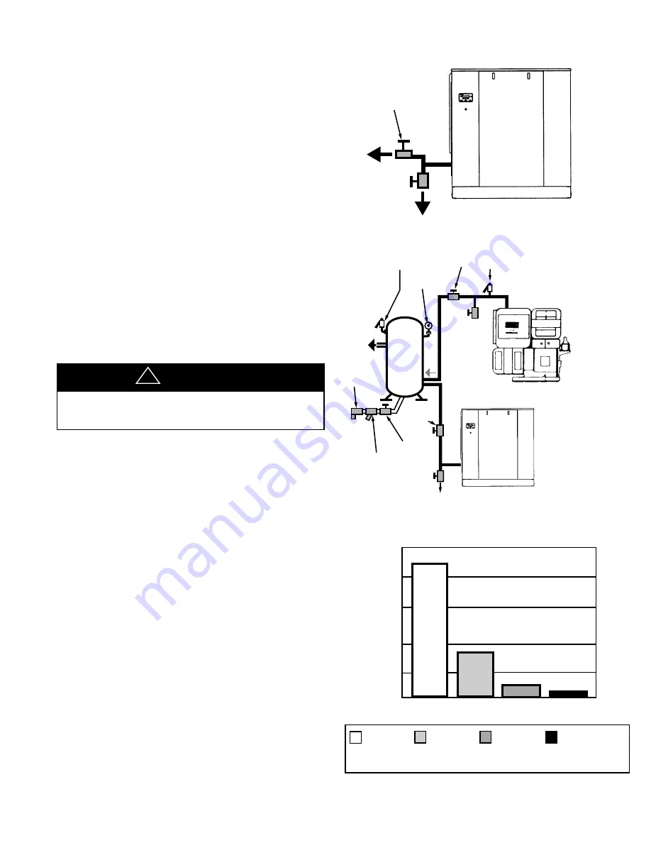
ISOLATION
VALVE
DRIP LEG
DISCHARGE PIPING WITH AFTERCOOLER
ISOLATION
VALVE
ISOLATION
VALVE
STRAINER
TRAP
NOTE:
SEPARATE LINES
GOING TO THE
RECEIVER
DRIP
LEG
ROTARY
COMPRESSOR
PRESSURE
GAUGE
SAFETY
VALVE
ISOLATION
VALVE
RECIPROCATING
COMPRESSOR
DRIP
LEG
SAFETY
VALVE
ROTARY-RECIP IN PARALLEL
Do not use the compressor
to support the discharge pipe.
Careful review of piping size from the compressor
connection point is essential. Length of pipe, size of pipe,
number and type of fittings and valves must be
considered for optimum efficiency of your compressor.
It is essential when installing a new compressor to review
the total plant air system. This is to ensure a safe and
effective total system.
Liquid water occurs naturally in air lines as a result of
compression. Moisture vapor in ambient air is
concentrated when pressurized and condenses when
cooled in downstream air piping.
Moisture in compressed air is responsible for costly
problems in almost every application that relies on
compressed air. Some common problems caused by
moisture are rusting and scaling in pipelines, clogging of
instruments, sticking of control valves, and freezing of
outdoor compressed air lines. Any of these could result in
partial or total plant shutdown.
Compressed air dryers reduce the water vapor con-
centration and prevent liquid water formation in
compressed air lines. Dryers are a necessary companion
to filters, aftercoolers, and automatic drains for improving
the productivity of compressed air systems.
NOTICE
!
2.3 PIPING (Continued)
A dripleg assembly and isolation valve should be
mounted near the compressor discharge. A drain line
should be connected to the condensate drain.
IMPORTANT: The drain line must slope downward from
the compressor to work properly.
NOTE: For ease of inspection of the automatic drain trap
operation, the drain piping should include an open funnel.
It is possible that additional condensation can occur if the
downstream piping cools the air even further and low
points in the piping systems should be provided with
driplegs and traps.
IMPORTANT: Discharge piping should be at least as
large as the discharge connection at the compressor
enclosure. All piping and fittings must be suitable for the
maximum operating temperature of the unit and, at a
minimum, rated for the same pressure as the compressor
sump tank.
MOISTURE CONTENT OF COMPRESSED AIR
200
160
120
80
40
0
DEW POINT
without
Aftercooling
100°F/38°C
(with
Aftercooler)
35°F /1.7°C
(Refrigerated
Dryer)
-40°F/-40°C
(Desiccant
Dryer)
Gallons of
W
ater/24
hour
s/1000 acfm
Summary of Contents for EP 60
Page 18: ...16 FIGURE 2 5 1 TYPICAL OUTDOOR SHELTERED INSTALLATION ...
Page 31: ...29 NOTES ...
Page 44: ...42 7 0 REFERENCE DRAWINGS 7 1 ELECTRICAL SCHEMATIC FULL VOLTAGE 39899794 REV 02 ...
Page 45: ...43 7 2 ELECTRICAL SCHEMATIC STAR DELTA 39899786 REV 02 ...
Page 46: ...44 7 3 FOUNDATION PLAN AIR COOLED 39894472 REV 03 ...
Page 47: ...45 7 4 FOUNDATION PLAN WATER COOLED 39907894 REV 03 ...
Page 48: ...46 7 5 FOUNDATION PLAN OUTDOOR MOD 39907886 REV 03 ...
Page 49: ...7 6 BASIC FLOW SCHEMATIC AIR COOLED 39899828 REV 02 47 ...
Page 50: ...48 7 7 BASIC FLOW SCHEMATIC WATER COOLED 39899836 REV 02 ...
Page 51: ...49 7 8 TYPICAL SYSTEM FLOW DIAGRAMS TYPICAL SYSTEM FLOW DIAGRAM ...
Page 52: ...50 7 8 TYPICAL SYSTEM FLOW DIAGRAMS ...
Page 53: ...51 7 8 TYPICAL SYSTEM FLOW DIAGRAMS ...
Page 54: ...52 7 8 TYPICAL SYSTEM FLOW DIAGRAMS ...
Page 55: ...53 7 8 TYPICAL SYSTEM FLOW DIAGRAMS ...
Page 59: ...57 DATE RUN TIME WORK DONE QTY UNIT WORK HOURS MEASURE BY 9 0 MAINTENANCE RECORD ...
Page 60: ...DATE RUN TIME WORK DONE QTY UNIT WORK HOURS MEASURE BY MAINTENANCE RECORD 58 ...
Page 61: ...59 DATE RUN TIME WORK DONE QTY UNIT WORK HOURS MEASURE BY MAINTENANCE RECORD ...
Page 62: ...60 DATE RUN TIME WORK DONE QTY UNIT WORK HOURS MEASURE BY MAINTENANCE RECORD ...


