04581245_ed2
5
13. Using a 1/2” wrench on one of the Spindle Bearing Nuts
(59), thread the Nut with the Coupling Retaining Ring (60),
counterbored end leading, onto the Spindle. Tighten the Nut
between 14 and 19 ft–lb (19.0 and 25.8 Nm) torque.
14. Install the two Rear Spindle Bearing Washers (63) in the Extension
Housing in the rear spindle bearing cavity.
15. Insert the assembled Spindle, Nut end leading, into the small end
of the Extension Housing. Push the assembly into the Housing
until the Rear Spindle Bearing bottoms against the Rear Spindle
Bearing Washers.
16. Grasp the assembled Motor Housing, mounted in Clamp Tool
(96), in soft-sided vise jaws with the Spindle Bearing Nut upward.
Coat the inside of the Arbor Coupling (57) with approximately 1
cm3 of Ingersoll Rand No. 68 Grease and install the Coupling over
the Bearing Nut. Position the Clamp Sleeve (58) over the Coupling
in the Motor Housing.
17. Insert the Spindle Bearing Nut in the assembled Extension
Housing into the Arbor Coupling and thread the Extension
Housing onto the Motor Housing. This is a left-hand thread; rotate
the Extension Housing counterclockwise to tighten it. Tighten the
Housing between 20 and 25 ft–lb (27.1 and 33.9 Nm) torque.
Assembly of the Angle Head
If the Upper Arbor Bearing (52 or 71) was removed and a new
Bearing must be installed, proceed as follows:
a. Support the machined face of the Angle Head (48 or 67) on
the table of an arbor press with the upper arbor bearing bore
upward.
NOTICE
When installing the Bearing in the next step, always press on the
stamped or closed end of the Bearing.
NOTICE
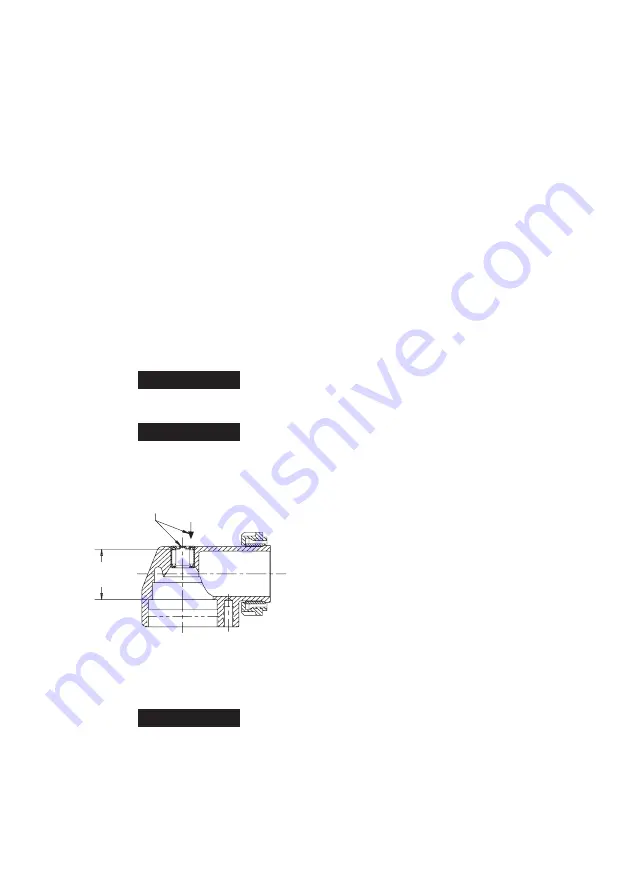
Do not press the Upper Arbor Bearing flush with the top of the
Angle Housing. Press the Bearing to the dimensions given in the
following step.
b. Press a new Upper Arbor Bearing into the bore.
PRESS IN UPPER ARBOR BEARING
TO DIMENSION SHOWN
1.002
.997
2. If the Lower Arbor Bearing (55 or 74) is being installed, it is
necessary to note the identification marks on the Lower Arbor
Bearing. One side of the Bearing has stains or hash marks across
the inner and outer races. Using a sleeve that contacts the inner
ring of the Lower Arbor Bearing, press the Bearing, stain or hash
mark side leading, onto the Arbor (76).
NOTICE
The Bevel Gear and Bevel Pinion in the next step are specially
matched sets. Some sets are color coded for manufacturing
purposes only. Only the Gear and Pinion set furnished as a
replacement part or the same Gear and Pinion set removed from
one tool is a matched set. A Bevel Gear from one tool and a Bevel
Pinion from another tool with the same color code IS NOT A
MATCHED SET. Replace these parts only as a matched set. Failure
to do so will result in unsatisfactory tool performance and
damage to the Bevel Gear and Bevel Pinion.
1.
3. Slide the Bevel Gear (47 or 66), geared face trailing, onto the small
threaded end of the Arbor, aligning the integral keys or spline of
the Gear with the slotted keyways or spline in the Arbor.
4. Thoroughly clean the small threads on the Arbor above the Bevel
Gear and the threads in the Bevel Gear Nut (54 or 73).
5. Apply a thin coat of Loctite 277* (M. I. Hernon Grade 429) to the
threads of the Bevel Gear Nut and the Nut threads on the Arbor.
Thread the Bevel Gear Nut onto the Arbor to retain the Bevel Gear
and tighten the Nut to 8 to 9 ft-lb (10.8 to 12.2 Nm) torque.
6. Form the Wick (53 or 72) into a horseshoe shape and fully insert it
into the U-shaped cavity in the Angle Head. If installing one of the
Wicks having a notch on one side, make certain the notch enters
the Housing first. Saturate the Wick with approximately 1.5 cm3
of
Ingersoll Rand
No. 63 Oil.
Do not substitute any other oil
.
7. Inject 3 cm3 of
Ingersoll Rand
No. 67 Grease into the Upper
Arbor Bearing and Wick cavity in the Angle Head.
Do not
substitute any other grease
.
8. Carefully grasp the assembled Motor Housing, mounted in Clamp
Tool in soft-sided vise jaws with the Throttle Lever
downward.
9. Install the motor Clamp Nut (50 or 69), threaded end trailing, onto
the motor end of the Angle Head. Spread the Clamp Spacer (49 or
68) and install it, beveled end trailing, onto the motor end of the
Angle Head against the Clamp Nut.
10. Position the output end of the Angle Head upward and 180
degrees opposite to the Throttle Lever and thread the Clamp
Nut onto the Cylinder or Extension Housing. Using the Clamp
Nut Wrench (95), tighten the Nut to 20 to 25 ft-lb (27 to 34 Nm)
torque. This is a
left-hand thread
, turn
counterclockwise
to
tighten.
11. Thoroughly clean the internal threads of the Angle Head and the
threads on the Arbor Bearing Cap (56 or 75).
12. Insert the assembled Arbor into the Angle Head, bevel gear
end first, making sure the teeth on the Bevel Gear and Pinion
mesh. Rotate the Arbor manually to determine they are rotating
smoothly.
13. Carefully apply a thin coat of Loctite 277 to both sets of threads.
14.
For G2A and G2L models
, using a spanner wrench, install
the Arbor Bearing Cap and tighten to 12 to 15 ft-lb (16.2 to
20.3 Nm) torque. The Bearing Cap has a
lefthand thread
: turn
counterclockwise
to install.
For G2E models
, using the Arbor
Bearing Cap Wrench (92), install the Arbor Bearing Cap and
tighten to 12 to 15 ft-lb (16.2 to 20.3 Nm) torque. The Bearing Cap
has a lefthand thread: turn counterclockwise to install.
Assembly Instructions for All Collet Models
Install the Collet (77) into the end of the Arbor.
Using the Collet Body Wrench (89) to hold the Arbor, thread the
Collet Nut (78) onto the Arbor.
Assembly Instructions for All Wheel Models
Position the Wheel Guard (81) against the flat face of the Guard
Adapter Assembly (79) and using a 1/8” hex wrench, install the
three Guard Mounting Screws (83) and Lock Washers (82). Tighten
the Screws to 2.5 to 3.0 ft-lb (3.4 to 4.1 Nm) torque.
For Models
Ending in P96 and P106
, Guard is only available as an assembly
and is mounted on the Guard Adapter with permanent thread
locker on the Guard Mounting Screws.
Position the Guard Adapter Assembly (79) recessed surface
leading, on the hub at the spindle end of the Angle Head and
using a 9/64” hex wrench, tighten the Wheel Guard Adapter Screw
(80) to 6 to 6.5 ft-lb (8.1 to 8.8 Nm) torque.
For Models, ending in P63, P64 and P74,
thread the Flange
Spacer (86) onto the Arbor and using the Arbor Wrench (91) to
hold the Arbor, tighten the Spacer with the second Arbor Wrench
(89).
For Models ending in P63, P64, P74, P1045, P105, and P106,
install Flange Spacer (86) (P1045, P105 and P106 models only),
the Wheel Flange (84), wheel and Flange Nut (85) on the Arbor.
Use the Arbor Wrench (91) to hold the Arbor while tightening the
Flange Nut with the Flange Nut Wrench (93).
For models ending in P945, P95 and P96
, install the Wheel
1.
2.
1.
2.
3.
4.
5.


