background image


WebPOS iWP220/ iWP250_user guide  


 7/20   


Copyright © 2009 Ingenico


9000002528 R11 000 01/926 


All rights reserved


4.


Installation and connection 

4.1.


Positioning the terminal 

Install the terminal on a flat surface, with an easy access to an electrical outlet. Place the 
terminal  away  from  any  heat  source  and  protected  from  dust,  vibrations  and 
electromagnetic radiations (away from video terminals, PC, anti-shoplifting barriers ...). 

Operating conditions  

Ambient temperature 

from +5°C to +40°C 

Max relative humidity 

85% at +40°C 

Storage conditions  

Storage temperature 

-20°C, +55°C 

Max relative humidity 

85% at +55°C 

4.2.


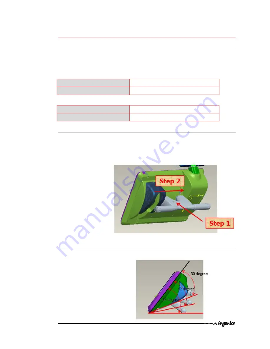
Support foot assembly 


Insert the foot in the 

foot support slot 

of iWP terminal (see slots on connections sketch 

4.4)


And translate the foot with horizontal direction to lock position 


4.3.


Three position available 


Insert  the  foot  in  one  of  the  3  foot

  support  slots 

of  iWP  terminal  (see  slots  on 

connections sketch 4.4)


Summary of Contents for WebPOS iWP220

Page 1: ...INGENICO 192 avenue Charles de Gaulle 92200 Neuilly sur Seine FRANCE T l 33 0 1 46 25 82 00 Fax 33 0 1 47 72 56 95 www ingenico com WebPOS iWP220 iWP250 U s e r G u i d e...

Page 2: ...e the shield cover___________________________________________________________ 9 4 5 3 Remove the shield cover ________________________________________________________ 9 4 6 Installing Micro SD Memory...

Page 3: ...operations only to an authorized person Failure to comply with these instructions will void the manufacturer s responsibility 2 Unpacking ADVICE Carefully preserve the packaging of the iWP220 iWP250...

Page 4: ...ports on your terminal or associated equipment or any other part of your terminal Such checks would provide warning of any unauthorized modifications to your terminal and other suspicious behavior of...

Page 5: ...an outlet on a circuit different from that to which the receiver is connected Consult the dealer or an experienced radio TV technician for help The device complies with part 15 of the FCC rules Opera...

Page 6: ...e approx 133 x 59 x 35 mm L x w x h Class II equipment PSU 2 pole socket 3 A Electrical mains network 100 240VAC 50 60 Hz Max consumption 2 5 A RMS Cable length Power block cable approx 1 3 m Display...

Page 7: ...iations away from video terminals PC anti shoplifting barriers Operating conditions Ambient temperature from 5 C to 40 C Max relative humidity 85 at 40 C Storage conditions Storage temperature 20 C 55...

Page 8: ...supply to the main power supply network Insert the cable in the Locking Mechanism 4 4 Connections All connections are on the rear of the terminal protected by a shield cover 4 5 Installing the iWP220...

Page 9: ...d close the cable cover as indicated by arrow on the figure below 4 5 3 Remove the cable cover Remove the cable cover by drawing on the clips 1 Lift the cable cover rearward to remove it as shown by a...

Page 10: ...10 20 Copyright 2009 Ingenico 9000002528 R11 000 01 926 All rights reserved 4 7 Reset button location Reset button is located under the terminal This button is hidden to avoid unexpected action Pleas...

Page 11: ...1 Open the cover paper compartment Open the paper compartment by pushing the button on the front face and pull the cover to the rear of the terminal CAUTION Do not force the cover against end stop ed...

Page 12: ...the rear side of the device Open the paper compartment by pushing the button on the front face and pull the cover to the rear of the terminal CAUTION Do not force the cover against stop edge Introduce...

Page 13: ...009 Ingenico 9000002528 R11 000 01 926 All rights reserved Connect the cable as shown below 1 Place correctly the cable into its different location 2 to avoid paper jam CAUTION You have to double chec...

Page 14: ...7 1 1 Reading a magstripe card Insert the card manually in the driver magnetic stripe facing right Swipe the card at appropriate speed to maximize the reading and avoid annoying repetitions 7 1 2 Con...

Page 15: ...cates that the product is powered Printer error Blinking indicates an error Cover paper not closed Out of paper Internal printer default Ethernet ON indicates LAN connected Blinking indicates data tra...

Page 16: ...d be introduce hit the sensitive area Default username admin Default password admin Do not forget to change the password after first login If you are the administrator the following screen is displaye...

Page 17: ...onditioner humidity higher than 85 exposure to sunlight or ultraviolet for long periods contact with organic solvents solvent type adhesive direct contact with materials containing plasticizers PVC tr...

Page 18: ...8 3 Transport and storage Use the original packaging for any unit or stored Disconnect all cables from the terminal during the transport 8 4 Troubleshooting The terminal does not turn on or does not c...

Page 19: ...wheeled bin printed on the product gives the information about the requirement not to dispose of WEEE as unsorted municipal waste and to collect such WEEE separately To assure that the product is col...

Page 20: ...rmission of INGENICO If such permission is granted it will be subject to the condition that the recipient ensures that any other recipient of this document or information contained therein is held res...

Reviews: