background image


IPA280 – User guide 


  22/43   

Copyright © 2010 Ingenico 


9000002522 R11 000 02/1002 


All rights reserved 


5.5.3.


Reading  Contactless Card 


PDA contactless is dedicated for user ID, transportation tickets and cards controls, 
RFID labels reading, loyalty cards reading, … 
It is not meant to be used for contactless payment  


5.5.4.


Reading  Contactless Payment card 


SPM contactless is dedicated to contactless payment.  


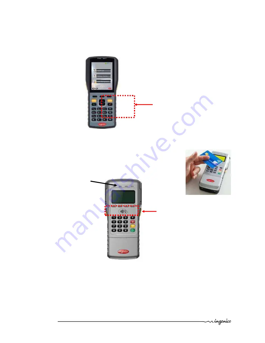
As the contactless antenna is placed around the display and keypads, the contactless card 
must  be  presented  in  front  of  Contactless  logo  between  the  screen  to  perform  the 
transaction. 
The 4 green LEDs indicate that the transaction is completed.  


Contactless card 
positioning 

Contactless 

LEDs 

Contactless  payment 
card positioning 

Summary of Contents for iPA280

Page 1: ...Ingenico 190 192 Avenue Charles de Gaulle 92200 Neuilly sur Seine Tél 33 0 1 46 25 82 00 Fax 33 0 1 47 72 56 95 www ingenico com iPA280 U s e r G u i d e ...

Page 2: ...______________ 8 3 4 3 FCC Hearing Aid Compatibility HAC Regulations for Wireless Devices ___________________ 9 3 5 Water protection_____________________________________________________ 10 3 6 Main Characteristics __________________________________________________ 11 4 Installation and connection _____________________________________12 4 1 Battery __________________________________________________...

Page 3: ...________________________ 25 5 7 1 1 Bluetooth ________________________________________________________________ 25 5 7 1 2 Wi Fi_____________________________________________________________________ 26 5 7 1 3 GPRS connection __________________________________________________________ 27 5 7 2 Ethernet_____________________________________________________________________ 28 5 7 3 Phone _______________...

Page 4: ...ransport and storage ________________________________________________39 6 4 Troubleshooting _____________________________________________________39 6 5 End of life___________________________________________________________39 7 Extensions and accessories ____________________________________ 40 7 1 Cradles _____________________________________________________________40 7 2 Holster __________________...

Page 5: ...ur terminal WARRANTY SECURITY To benefit from the guarantee related product and to respect the security we ask you to use only accessories delivered in box with the product or original Ingenico accessories entrusting maintenance operations only to an authorized person Failure to comply with these instructions will void the manufacturer s responsibility The IPA 280 terminal concept is This symbol i...

Page 6: ...cessories The iPA280 terminal The data and power cable The charging unit including region specific power plug The Paper roll The battery pack The user guide The smart card rubber cover and chord Stylus SPM Lock pin screws x2 The power supply unit provided with your equipment is specially designed for Ingenico iPA280 terminals Do not use any other power supply Power Adaptor Data and power cable Pap...

Page 7: ...s that have access to your terminal You are strongly advised to ensure that privileged access to your terminal is only granted to staff that have been independently verified as being trustworthy 3 3 EC standard compliance marking EC standard compliance marking certifies that the product stipulated below iPA280 complies with the basic requirements of European Directive 1999 5 CE known as the R TTE ...

Page 8: ...es cause harmful interference to radio or television reception which can be determined by turning the equipment off and on the user is encouraged to try to correct the interference by one or more of the following measures Reorient or relocate the receiving antenna Increase the separation between the equipment and receiver Connect the equipment into an outlet on a circuit different from that to whi...

Page 9: ...evices Not all phones have been rated Phones that are rated have the rating on their box or a label located on the box The ratings are not guarantees Results will vary depending on the user s hearing device and hearing loss If your hearing device happens to be vulnerable to interference you may not be able to use a rated phone successfully Trying out the phone with your hearing device is the best ...

Page 10: ...al SD Card lid The SD card lid is located on the side of the terminal must be in place during normal operation of the terminal Cable lid The cable lid is located under the terminal see chapter Installing the iPA280 must be in place during normal operation of the terminal It shall be in connection configuration when the iPA280 is connected into the cradle SPM Smart Card Rubber Cover A cover for the...

Page 11: ...d 2412 2472MHz for EU used WWAN 900 1800MHz for EU used 850 1900MHz for US used SPM part Weight 160 g Dimensions 140 x 86x 20 mm l x w x h Cable length Power block cable approx 1 3 m Display Type Graphical TFT color Display area active zone 3 5 Number of pixels 480 x 640 Technology Transflective Backlight LED Brightness 180 cd m Contrast 1 1500 Number of colors 262k Operating conditions Charging t...

Page 12: ...re aligned with the contacts in the compartment as shown in the following illustration Place the battery pack into the battery bay and press the battery securely into the compartment Close the device by fitting back the SPM see section 4 2 WARNING There is a risk of fire and burns if the battery pack is handled improperly DO NOT disassembles crush puncture short external contacts or dispose the ba...

Page 13: ...ct the SPM part to the iPA280 terminal Insert the SPM part to connect the USB connector then slide down then lock it using the two side levers User can secure the SPM assembly using two standard screws size M1 6xL3 delivered with the unit as indicated in the picture The screws prevent too easy access to the battery SIM and SAMs A tool has to be used to remove the SPM in that case The SPM is now co...

Page 14: ...lot to the end until you hear a click To remove SAM we suggest you to use a piece of adhesive previously pasted on both sides of the SAM as shown here below 4 4 Installing PDA SAM and SIM The PDA side has two slots for SIM cards and two slots for SAM cards They are placed inside the battery compartment in the rear of the terminal see procedure to opening 4 1 Lift the battery as shown in the follow...

Page 15: ...ng picture 4 5 Installing Micro SD Memory Micro SD Memory slot is located at the right side of the terminal Insert completely the micro SD memory card in the slot Be careful of the insertion direction See the illustration below To remove the Micro SD Memory Card push on it with your nails or stylus MicroSD Memory slot SIM2 Slot SIM1 Slot SAM1 Slot SAM0 Slot ...

Page 16: ...ert the paper roll in the compartment Make sure that GPRS antenna is located in its protective film Unroll the paper out of the compartment and hold it in bottom position as illustrated Maintain the paper and close the cover Press in the middle of the cover to close it 4 7 Connections Establishing Device PC Connection o Installing Microsoft ActiveSync In order to exchange data between your compute...

Page 17: ...automatically and configure the USB port to work with the iPA280 The New Partnership setup wizard will automatically start NOTE If ActiveSync does not start automatically click Start Programs Microsoft ActiveSync If a message appears indicating that it is unable to detect a connection click the Cancel button and manually configure the communication settings 4 8 Positioning the terminal Place the t...

Page 18: ... Application specified 2 Programmable key 3 Navigation key 4 Navigation directions 1 Select center OK 4 Send End Send green Select Press opens the phone dialer application Press while a call is coming in Answer the call Press and Hold when on a call goes to speakerphone End red Press when in a call ends a call Press while a call is coming in Ignore the call Press and Hold ends the data connection ...

Page 19: ...Display Behaviour of LED on PDA side 2 LEDs for communications batteries and SPM If SIM inserted and device registered only GSM GPRS information available Left LED Right LED Charging RED Charged GREEN Battery Low RED Flash System power 15 0 3 s on 1 7 s off Printer power low 0 3 s on 0 55 s off Printer power cut off 0 3 s on 0 3 s off Blue Tooth BLUE Flash On 0 5 s Off 5 s WiFi BLUE Flash On 0 5 s...

Page 20: ...rease or decrease the phone volume When phone call is not active press to increase or decrease the PDA volume Reset You may have to perform a reset if the device freezes i e device no longer responds to the buttons or tapping on the screen A soft reset allows your device to get a fresh start similar to rebooting a computer This will restart your device All records and entries are retained after a ...

Page 21: ...lot magstripe from right side to left side or from left to right side Swipe the card with constant speed to maximize the reading and avoid annoying repetitions 5 5 2 Reading a smart card Turn to SPM right side take out the smart card rubber and insert the Smart card to the end of the slot chip facing up to read the card information Magnetic stripe card slot Smart card slot Magnetic stripe position...

Page 22: ...ot meant to be used for contactless payment 5 5 4 Reading Contactless Payment card SPM contactless is dedicated to contactless payment As the contactless antenna is placed around the display and keypads the contactless card must be presented in front of Contactless logo between the screen to perform the transaction The 4 green LEDs indicate that the transaction is completed Contactless card positi...

Page 23: ...es 5 6 1 Login sequence After powering on the device connect the power ON OFF button on top of the device This sequence will also happen after inserting a charged battery the following screens are chained CAUTION Do not press the green key until password and username are entered A username and a password should be introduce hit the sensitive area Default username admin Default password admin Do no...

Page 24: ...tion selected by the administrator is installed this application is automatically launched at device power up 5 6 2 Main System When the power off device is plugged in with the power cord the boot screen with Ingenico logo is shown After several seconds the next system selection screen will automatically be displayed The user can select one of WinCE OS Main System or 3rd Party Systems from here Af...

Page 25: ...g 5 7 1 Wireless network You can use Connectivity menu to select the desired Wireless Networking function 5 7 1 1 Bluetooth Click the BT button in Connectivity menu to turn on off Bluetooth function Click one of item in Untrusted or Trused list in BT menu to select the desired Bluetooth device to be connected ...

Page 26: ...d 5 7 1 2 Wi Fi Click the Wi Fi button in the Connectivity menu to turn on off Wi Fi function Click one of item in Wi Fi List in Wi Fi menu to select the desired Wi Fi device to be connected Double click the selected item in Wi Fi List to display the Wi Fi Information as in the following screen ...

Page 27: ...d 5 7 1 3 GPRS connection Click the GPRS button in the Connectivity menu Enter the PIN number from SIM card and click OK button in the next two screens Enter a random data in the Enter Connection Name box and internet in the Access Name box and click OK button to enable GPRS connection function ...

Page 28: ... rights reserved 5 7 2 Ethernet Click the Ethernet button in the Connectivity menu Enter IP Address and Default Gateway in the boxes of the dialog and click OK button to the next screen Enter DNS and WINS in the boxes of the dialog and click OK button to enable Ethernet function ...

Page 29: ... do one of the following 1 Tap Phone on the bottom left corner of the screen 2 Press Talk Send button Press Cancel button when you want to exit the Phone Dialer screen The Phone Dialer screen opens From here you can create Speed Dials get the Call History and customize phone settings NOTE If your SIM card is protected by a PIN code input the password before you can use the phone Tap the antenna si...

Page 30: ...right 2010 Ingenico 9000002522 R11 000 02 1002 All rights reserved Click the Speed Dialler button in Phone Dialler menu to go to Speed Dialler screen Click the Call History button in Phone Dialler menu to go to Call History screen ...

Page 31: ...r button in Phone Dialer menu to make the phone and to get the dialing Phone Dialer screen During the dialing status the iPA280 can still use WLAN BT RFID at the same time 5 7 4 Factory Reset o Click the button to get the Factory Reset screen Click OK button to have the device system back to the factory setting ...

Page 32: ...02522 R11 000 02 1002 All rights reserved 5 7 5 Language o Click the button to get the Language screen Select the desired language and click OK button to change the language in the device 5 7 6 System Info o Click the button to get the System Info screen ...

Page 33: ...ime Setting screen 5 7 8 Barcode Reader Press Right and Left scanner trigger buttons to activate the barcode scanner LED indicates the battery charging and barcode scanning status o Green Battery is fully charged or barcode scanning process is completed without error o Red Battery is charging barcode scanner is fired activated Barcode scanner setting ...
Page 34: ...IPA280 User guide 34 43 Copyright 2010 Ingenico 9000002522 R11 000 02 1002 All rights reserved o Click the button to get the System menu Click the button to get the Barcode menu ...

Page 35: ... 128 3 DataMatrix 4 EAN UPC Symbology can read 1 Code39 2 Code128 GS1 128 3 DataMatrix 4 EAN UPC 5 Aztec 6 Codabar 7 Code11 8 Code93 9 EAN add on 2 10 Interleave 2 of 5 11 Matrix 2 of 5 12 Plessey 13 GS1 DataBar 14 Standard 2 of 5 15 Telepen 16 QRCode 17 Maxicode 18 MicroPDF417 PARAF can read 19 PARAF code TriopticNCodablock can read 1 Code39 2 Code128 GS1 128 3 DataMatrix 4 EAN UPC 20 Trioptic 21...

Page 36: ...king station CAUTION Operating the iPA280 for the first time without the AC adapter and without fully charging the backup battery may result in loss of data stored in RAM memory When the main battery is removed the backup battery retains date and time for at least 10 minutes 5 8 2 Normal mode Device is on and running It is receiving full power from the system and is delivering full functionality t...

Page 37: ...le of raising the system power state on its own It consumes only enough power to be able to do so LCD is off and LED flashes in green every 2 seconds 5 8 5 Deep sleep Device has no power A device in Deep Sleep mode should not be consuming any significant power Some peripheral busses require static terminations that intrinsically use non zero power when a device is physically connected to the bus L...

Page 38: ...ype adhesive direct contact with materials containing plasticizers PVC transparent folders or envelopes direct contact with diazo papers direct contact with water Rubbing or pressing the paper too strongly CAUTION In order to benefit from the complete guarantee of the product only heat sensitized paper approved by the manufacturer can be used 6 2 Cleaning of the terminal First of all unplug all th...

Page 39: ...Possibly adjust the paper roll following instructions present in it s manual Check the type of paper used thermal paper must be used 6 5 End of life The product belongs to the family of electrical and electronic equipment Therefore it is subjected to the WEEE directive which requires the collection and the recycling at the end of life product The Ingenico products present the symbol for the markin...

Page 40: ...le into the power jack on the cradle then connect the AC adapter into an electrical outlet o Before slide the device into cradle remove the grommet of the terminal see location on illustration in order to establish the connection with cradle o The connection is secure when the bottom edge of the device is aligned with the cradle and the LED indicator on the device lights up red Grommet Paper exit ...

Page 41: ...guide 41 43 Copyright 2010 Ingenico 9000002522 R11 000 02 1002 All rights reserved 7 2 Holster The Holster can hold two paper rolls on both side The front pocket can hold a iPA280 battery the paper roll the battery ...

Page 42: ... All rights reserved 7 3 Pistol Pistol Grip handle for inventory management purpose Data capture through trigger Easy snap on PDA To install the pistol on PDA remove the SPM part see section 4 1 and slide the pistol in the PDA part as illustrated by arrows on the illustration ...

Page 43: ...such permission is granted it will be subject to the condition that the recipient ensures that any other recipient of this document or information contained therein is held responsible to INGENICO for the confidentiality of that information Care has been taken to ensure that the content of this document is as accurate as possible INGENICO however declines any responsibility for inaccurate incomple...

Reviews: