


M2M Control CX320 Technical Manual V1.01
Page 21 of 42
Analog Outputs
The M2M Control CX320 has two analog outputs, which can be configured individually to work
either as voltage or current outputs using the configuration jumpers. The range in voltage mode is
0..10 VDC, and in current mode 0..20mA. The resolution of the digital-to-analog converter is 10bit or
1024 in decimal scale.
The decimal value for 10V/20mA output is 1023, and 512 for 5V/10mA.
The output signal is connected to the external equipment between AOUTx and AGND. AGND must
be connected to the reference of the connected equipment. Please be aware that deviations may occur,
as the system is very noise-sensitive. Avoid long unshielded wires and significant fast-changing
signals routed parallel to the analog signals. In current mode, the specifications for the analog output
are only valid for a maximum load is maximum of 250Ω.
The inputs are low-pass filtered, ESD- and transient protected.
Please notice:
The M2M Control CX320 unit must be supplied with a minimum of 12VDC in order for
the analog outputs to work according to the specifications.
By default, the outputs are configured as voltage outputs. For replacement and configuration of the
hardware jumpers inside the device, please refer to the device configuration guide in Appendix D.
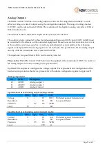
Analog output pins
Pin
Name
Description
20
AOUT1
Analog output 1
21
AOUT2
Analog output 2
26
AGND
Analog Ground
Specification for each analog output (voltage mode):
Min.
Typ.
Max.
Unit
Voltage
0
-
10
VDC
Protected against transients and
low-pass filtered
Resolution
-
-
10
Bit
Precision
-
0.5
0.8
%FSR
Load
10
-
-
kΩ
Specification for each analog output (current mode):
Min.
Typ.
Max.
Unit
Current
0
-
20
mA
Protected against transients and
low-pass filtered
Resolution
-
-
10
Bit
Precision
-
0.5
0.8
%FSR
Load
-
-
250
Ω


