


M2M Control CX320 Technical Manual V1.01
Page 12 of 42
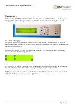
The user interface can be found on the front and consists of a 144x32 easy-to-read graphical LCD, a
keypad with eight keys, four user-controlled LEDs, and three system LEDs.
The graphical LCD can show information to the user with both text and graphics fully supported. In
addition, the LCD also has icons for battery level/charging-in-progress and network status.
The keypad can let the user interact with the LX4 pro and access the system menu.
Front-side view
The pluggable screw terminals on the top and bottom sides of the LX4 pro are used to make
connections to external equipment.
All the connectors are available externally for easy access and maintenance.
The bottom side of the M2M Control CX320 has connectors for the following communication
interfaces: Ethernet, 1-Wire, RS232, RS485 Port 1 and Port 2, and wired M-Bus. The analog
inputs/outputs are also found on this side.
Bottom-side view
Graphical LCD 144x32
Keypad
LEDs
Pin 5 . . . . . . . . . . . . . . Pin 26
Pin 27 . . . . . . . . . . . . . . Pin 49
Reset Button
Ethernet
Connector Pin 5 . . . . . . . . . . . . . Pin 26
Screw
terminals
Screw
terminals


