


M2M Control CX320 Technical Manual V1.01
Page 17 of 42
Digital outputs
The digital outputs control eight "high-side" switches. They function like contacts, where one side is
connected to the positive supply of the CX320 unit, and the other side is to the output. The switches
are protected against short circuits, ESD, and electronic kickback from inductive loads such as a relay.
The maximum switchable inductance is 20mH and must not be exceeded.
The digital output control circuit is supplied from the power supply connected to the DOUT SUPP
and DOUT GND. The DOUT GND is connected with the system GND internally
The CX320 unit offers advanced power management that can enable one or more outputs while the
device is in low power mode. Please consult the M2M Control IDE documentation for additional
information.
Digital output pins
Pin
Name
Description
30
DOUT SUPP Digital output supply, positive (+) connector
31
DOUT 1
Digital output 1
32
DOUT 2
Digital output 2
33
DOUT 3
Digital output 3
34
DOUT 4
Digital output 4
35
DOUT 5
Digital output 5
36
DOUT 6
Digital output 6
37
DOUT 7
Digital output 7
38
DOUT 8
Digital output 8
39
DOUT GND
Digital output ground, negative (-) connector
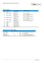
Specification for each digital output
Type
Min.
Max.
Unit
Push/Pull
0
36
VDC Short-circuit, Overload, Overvoltage, and ESD protected
-
1.5
A
-
140
mΩ
On-state resistor per channel


