


93
INFOSEC UPS SYSTEM
–
15, Rue du Moulin
–
44880 Sautron
–
France
–
www.infosec-ups.com
Hot Line Tel : +33 (0)2 40 76 15 82
–
fax : +33(0)2 40 94 29 51
–
–
02 19 AA 59 203 07
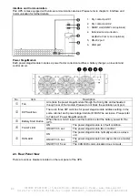
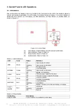
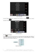
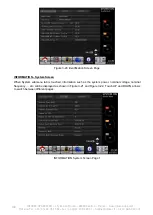
3. Control Panel & LCD Operations
3-1. Introduction
This control panel and display screen are located at the front panel of the UPS. This interface allows to
monitor all measured parameters, the UPS status, the battery status and alarms. The control interface is
divided into four sections: (1) LCD display, (2) LED indications, (3) Power Button, (4) Audible Alarm, as
shown in Figure 3-1.
Figure 3-1 Control Panel
(5)
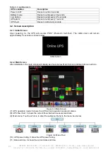
LCD display: Graphic display and all measured parameters.
(6)
LED indications. Refer to Table 3-1.
(7)
Power Button. Refer to Table 3-2.
(8)
Audible Alarm. Refer to Table 3-3.
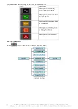
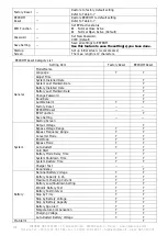
Table 3-1: LED Indications
LED
Color
Status
Definition
LINE
Green
On
Input source is normal.
Flashing
Input source is abnormal.
Off
No input source
BYPASS
Yellow
On
Load on Bypass.
Flashing
Input source is abnormal.
Off
Bypass not operating.
LOAD
Green
On
There is power output for the load.
Off
There is no power output for the load.
INV
Green
On
Load on inverters.
Off
Inverters not operating.
BATTERY
Red
On
Load on Battery.
Flashing
Low battery
Off
Battery converter is normal and battery is charging.
FAULT/
ALARM
Red
On
UPS fault.
Flashing
UPS alarm.
Off
Normal.
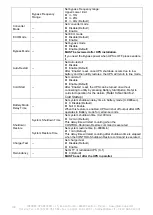
Table 3-2: Power Button
Control Key
Description
Power On/Off
Turn on UPS or Turn off UPS. (hold 2-Sec)


