background image

9

INSIGHT DLP

SENSOR 0610S Appliance Hardware Installation Guide

www.infolocktech.com


Small fixed
rack brackets

Long bracket

C

B

C

Two M4 truss head screws

One M4 truss
head screw

B

Small fixed
rack brackets

Small fixed

rack brackets with

threaded holes

A

A

M5 x 12 

f

l

at

head


scre

w

s

*

(

t

w

o


front


and

t

w

o


rear

A

A

A

A

B

B

7.

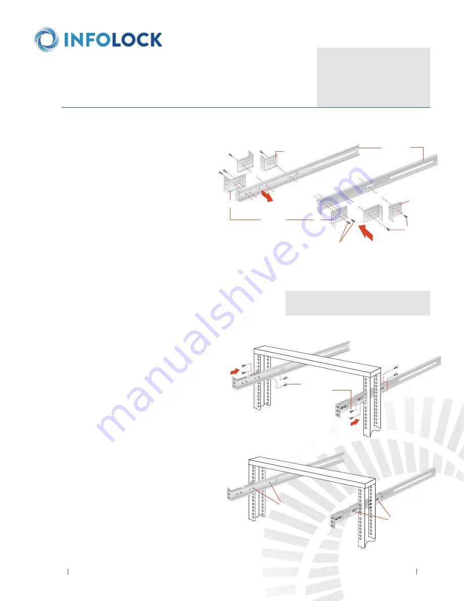
2-POST RACK INSTALLATION

Unpack the appliance and locate the mounting hardware

Step 1

Locate the two long and six short rack brackets that
came in your ship kit. 

A.

Securely attach the set of short brackets 
with the threaded screw holes to the 
long bracket in the front as shown. 
Use two M4 truss head screws for each 
bracket. 

B.

Loosely attach one set of the other short 
brackets to the long fixed bracket as 
shown using one M4 truss head screw on 
each bracket. The three holes on the flap 
will face toward the back for later 
attachment to the 2-post rack. 

C.

Loosely attach the remaining set of short 
brackets to the long fixed bracket as 
shown using one M4 truss head screw 
on each bracket. The three holes on the 
flap will face toward the front for later 
attachment to the 2-post rack. 

Step 2

Attach the assembled brackets to the 
2-post rack. 

A.

Insert two M5 x 12 flat head screws 
through the short brackets into the 
2-post rack (in the front and back of the 
rack as shown) and tighten. Make sure 
the brackets are aligned and level in 
height, not only in the front and back 
but also on the left and right sides.

B.

Tighten each of the single screws on the 
small fixed brackets (located on either side 
of the rack) to secure the brackets in the 
rack and ensure appliance stability. 

NOTE: 

Once the assembled rails are attached to the rack,

securely tighten the single screws on steps 

B

and 

C

.

NOTE:

The following installation procedures

for the 

2-Post Rack

are for use with the rails

and hardware provided in your ship kit. If 
different style rails are being used, or if your
rack requires different hardware, refer to the
instructions provided with your rail’s or rack’s
ship kit.

Summary of Contents for INSIGHT DLP SENSOR 0610S

Page 1: ...INSIGHT DLP SENSOR 0610S Appliance Hardware Installation Guide ...

Page 2: ...tion 4A 4 Post Rack Installation with Standard Rails 5 Section 4B 4 Post Rack Installation with Quick Mount Rails square hole rack only 6 Section 5 Installing the Appliance in the 4 Post Rack 7 Section 6 Unpacking the 2 Post Rack Installation Hardware 8 Section 7 2 Post Rack Installation 9 Section 8 Installing the Appliance in the 2 Post Rack 10 Section 9 Rear Panel Connections 11 Section 10 Front...

Page 3: ...ng jacks or stabilizers are properly attached to the rack If installing multiple appliances in a rack make sure the overall loading for each branch circuit does not exceed the rated capacity Do not slide more than one appliance out from the rack at a time Extending more than one appliance at a time may result in the rack becoming unstable Install your appliance in the lower part of the rack becaus...

Page 4: ...et of 4 post rack mounting hardware n A pair of 4 post rack sliding chassis rail rack assemblies that attach directly to the rack Installation Assembly B Quick Mount Rails for use in 4 post racks with square holes only n Two power cords n Two 10 32 x 3 4 Phillips pan head screws n A pair of adjustable quick mount rack rail assemblies requires no additional mounting hardware or tools Two 10 32 x 3 ...

Page 5: ...ick into place n Attach the rack rail assemblies to the rack using two M5 x 12 flat head screws and cone washers in the front and back The convex side of the cone washers face toward the rack n Make sure the rack rail assemblies and screws are aligned in the rack not only in the front and back but are level in height on the left and right sides for proper alignment for appliance installation Step ...

Page 6: ...e view Quick mount rail locking mechanism 4 post rack D C E A B Step 2 n Quick mount rail Installation in the square hole rack A Insert the quick mount rail tabs on the front of the rack rail assembly through the selected set of square holes in the rack B Push the tabs into the holes in the rack until you hear the locking mechanism on the rail assembly click into place The locking mechanism secure...

Page 7: ...ance with the fixed chassis rack rail assemblies previously installed in the rack n Carefully slide the appliance into the rack rails until you hear the locking tabs on the chassis rails click into place n Push the appliance all the way into the rack until it stops n Secure the unit in the rack by inserting and tightening two 10 32 x 3 4 Phillips pan head screws one on each side NOTE When removing...

Page 8: ...o the rack 2 Post Rack rail assembly outside view 2 Post Rack rail assembly inside view Eight M5 x 12 Phillips flat head screws Two 10 32 x 3 4 Phillips pan head screws used to secure the appliance in the rack Twenty two M4 x 4 Phillips truss head screws 6 UNPACKING THE 2 POST RACK INSTALLATION HARDWARE Verify that the ship kit includes the following installation hardware NOTE Use the hardware sup...

Page 9: ... the remaining set of short brackets to the long fixed bracket as shown using one M4 truss head screw on each bracket The three holes on the flap will face toward the front for later attachment to the 2 post rack Step 2 Attach the assembled brackets to the 2 post rack A Insert two M5 x 12 flat head screws through the short brackets into the 2 post rack in the front and back of the rack as shown an...

Page 10: ...ck rail assemblies previously installed in the rack n Carefully slide the appliance into the rack rails until you hear the locking tabs on the chassis rails click into place n Push the appliance all the way into the rack until it stops n Secure the unit in the rack by inserting and tightening two 10 32 x 3 4 Phillips pan head screws one on each side NOTE When removing the appliance from your rack ...

Page 11: ... 1 AC Power Inlet 1 Power Supply 2 AC Power Inlet 2 COM Port Remote Management Port Low Profile PCIe Expansion Slot eth3 Port DLP Port SPAN Port MGMT Port L M N O P Q R S T U V W Power Good LED 1 Power Supply Lock 1 Power Good LED 2 Power Supply Lock 2 USB Port 1 generation 2 USB Port 2 generation 2 USB Port 3 generation 3 USB Port 4 generation 3 eth4 Port eth5 Port VGA Port RAID Controller Card N...

Page 12: ...all outlet Step 1 Connect the Ethernet cables for MGMT DLP and SPAN if required Step 2 Connect any other required cables Step 3 Connect the power cords Proceed to Section 10 Front Panel Operation on page 13 POWER SUPPLY CONDITION Output ON and OK No AC power to both power supplies AC present Only 5VSB on PS off AC cord unplugged or AC power lost with a second power supply in parallel still with AC...

Page 13: ...tionLED Blue LED System identification indicator Red LED System alert indicator UID I O Power Button n t UnitIDButt ton 3 Power on the appliance 1 Remove the front bezel if it is on the appliance by pressing in on the left side of the bezel to release it from the appliance 2 Press the power button located on the far right on the front side of the appliance 3 Once the system has been powered on rep...

Page 14: ...2900 S QUINCY ST 330 ARLINGTON VA 22206 1 877 610 5625 Copyright 2018 Infolock All rights reserved ...

Reviews: