Copyright ©2018, Infoblox, Inc.All right reserved.
1.
2.
mount the appliance to a seismic rack, you also need the following:
M5 rack screws that fit the seismic rack
Round-hole M5 cage nuts for use with the seismic rack
A screwdriver
SFP/SFP+ Transceiver Installation and Removal Guidelines
After receiving a shipped Infoblox appliance appliance with SFP or SFP+ support, Infoblox recommends installing the transceivers into your
appliance before turning power on to the system for the first time. (This procedure is required for the Infoblox-4030-10GE appliance.) Pay heed to
the interface configuration required for your application (for related information, see
).
10-Gigabit Ethernet Connectivity
Should circumstances require you to ship an appliance to Infoblox for repair or replacement,
remove all SFP or SFP+ transceivers from your appli
. Keep your transceivers in your facility until the appliance is replaced or repaired and subsequently
ance before shipping it back to Infoblox
returned to you.
Rack Mounting Safety Requirements
The following space and airflow requirements are required for Infoblox-4030 and Infoblox-4030-10GE system operation:
Minimum clearance of 63.5 cm (25 in) in front of the rack
Minimum clearance of 76.2cm (30 in) in the rear of the rack
Minimum clearance of 121.9 cm (48 in) from the rack rear to the rear of another rack or row of racks
The appliance draws air in through the front of the chassis and expels air through the rear. Adequate ventilation is required to allow ambient room
air to enter the system chassis and to be expelled from the rear of the chassis.
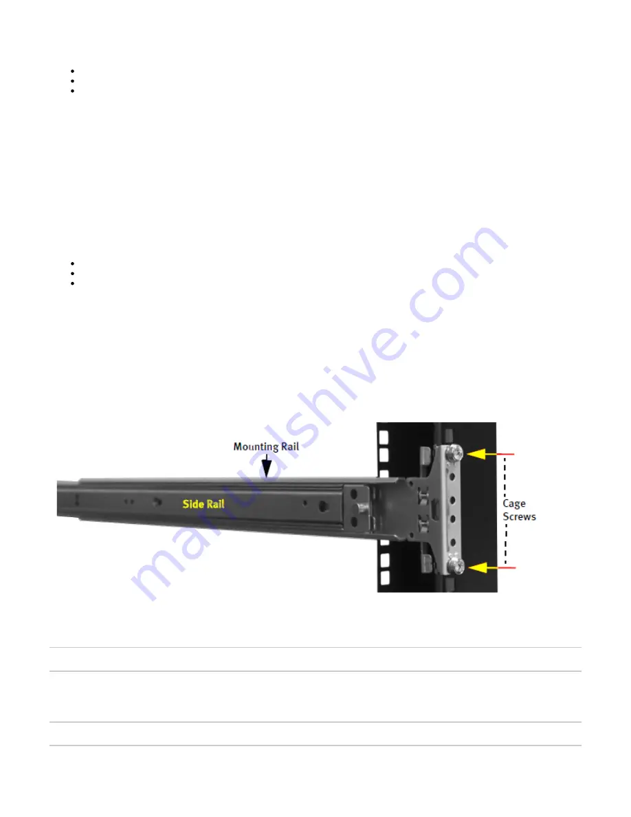
To mount the appliance to a seismic rack, do the following:
Unscrew the snap-in screws from the mounting rails and discard.
Install the round-hole M5 cage nuts in the appropriate rack hole positions where you want to install the appliance. Ensure that you install
two cage nuts on the front and two on the back of each rail, as shown in
. Note that the square-hole cage nuts that ship with the
Figure 7
accessory kit do not fit in the seismic rack.
Figure 7 Installing the Round-Hole M5 Cage Nuts
3. Line up a mounting rail with cage nuts, and attach the mounting rail to the rack with M5 screws. Ensure that the front end of each
mounting rail connects to the front of the rack.
Note: Ensure that both rail assemblies are correctly leveled.
4. Repeat steps 1 to 3 for the other mounting rail.
5. Slide out the side rails from each mounting rail and press the flange that holds each side rail in place. Then pull out each of the side rails
from the assembly.
Note: Make sure that you keep track of the front end of each rail.
6. Align each side rail to the appliance and snap them in place, as shown in
.
Figure 8


