background image

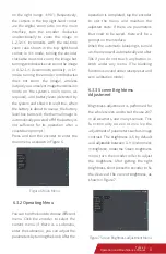
Figure 10 Zero Calibration

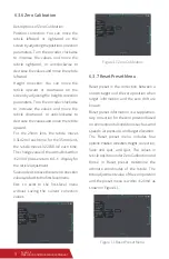
Figure 11 Reset Preset Menu

Reset  preset  is  the  correction  between  a 
known target and the zero position when 
target  information  and  the  zero  drift  are 
known. 
Reset preset information is a supplemen-
tary correction for the zero position based 
on environmental conditions such as wind 
speeds, air pressure, and target elevation.
The  Reset  preset  menu  includes  four 
options: Position correction, Height  correction, 
Save  and  quit,  and  Quit.  The  values  in 
reticle position under Zero Calibration and 
those  in  Reset  preset  determine  the 
ultimate  coordinates  of  the  reticle.  The 
total adjustment value of the zero position 
and the preset menu is within ±20mil, as 
shown in Figure 11.

 6.3.7 Reset Preset Menu

Descriptions of Zero Calibration
Position  correction:  You  can  move  the 
reticle  leftward  or  rightward  on  the 
screen by adjusting the position correction 
parameters. Turn the encoder clockwise 
to  increase  the  values  and  move  the 
reticle  rightward,  or  anticlockwise  to 
decrease the values and move the reticle 
leftward.
Height  correction:  You  can  move  the 
reticle  upward  or  downward  on  the 
screen by adjusting the height correction 
parameters. Turn the encoder clockwise 
to  increase  the  values  and  move  the 
reticle  downward,  or  anticlockwise  to 
decrease the values and move the reticle 
upward.
For  the  25mm  lens,  the  reticle  moves 
0.3142 mil each time; for the 35mm lens, 
the reticle moves 0.22038 mil each time. 
The change value of the azimuth is within 
±20mil; please return to 1×  display for 
the reticle adjustment.
Save and exit: to save the current correction 
values and exit to the first-level menu.
Exit:  to  exist  to  the  first-level  menu 
without  saving  the  current  correction 
values.

6.3.6 Zero Calibration

9

Tyke-L3 

Operation and Maintenance Manual 

Summary of Contents for Tyke-L3

Page 1: ...Tyke L3 Thermal Imager IRay Technology Co Ltd OperationandMaintenanceManual V1 0 2...

Page 2: ...d brush Do not wipe it with ngers or dirty cloth Protect the thermal imager from falling or severe impact Cautions Please do not power the thermal imager to reduce battery energy consumption when it i...

Page 3: ...peci cations 3 Package and Label 3 3 3 4 4 1 Focus Knob 4 2 Power Button 4 3 Encoder Aviation Connector Interface 4 4 4 Encoder 4 4 5 Diopter Regulation Knob 4 Functional Components and Interface 4 5...

Page 4: ...tion and Storage 9 Package List 13 12 12 8 1 Transportation 8 2 Storage 6 3 4 Image Transmission 6 3 5 Infrared Image 6 3 6 Zero Calibration 6 3 7 Reset Preset Menu 6 3 8 Reticle Setup 6 3 9 Other Set...

Page 5: ...tion adjustment g Reticle selection and adjustment h Auto detection of faults i Reverse polarity protection and over discharge protection for battery j Light leaking prevention The technical speci cat...

Page 6: ...ture StorageTemperature Humidity Altitude Encapsulation ReticleAdjustmentRange L325 L335 18650 Lithium battery 8h 190 76 82mm 450g 193 76 82mm 485g 10s IP67 400m 600m 600m 850m 15mil 40 55 50 70 95 3...

Page 7: ...a special white packaging box with black matte blister box as inner lining and foam at bottom which is not easy to be damaged during transportation For details please take package list for reference...

Page 8: ...to adjust the clarity of the display screen which can be adapted to the observation of myopia and hyperopia glasses 4 5 Diopter Regulation Knob The thermal imager is directly connected to the Picatin...

Page 9: ...Picture Caution it is not allowed to press the encoder during rotating After the battery is installed and can supply power normally long press the power button for 5 seconds to get the thermal imager...

Page 10: ...the Screen brightness menu turn the encoder roller to adjust the brightness After getting the right brightness short press the encoder to x the device at the current brightness as shown in Figure 7 o...

Page 11: ...ss approach for simultaneous observation coordinatedcommand andquickdirections Itcanbeperformedthrough head mounted transmission wireless transmission or analog videos disabled by default must be enab...

Page 12: ...e surrounding environment brightness Contrast adjustable between 0 100 0 by default Brightness and contrast ranges between 0 100 Turn the encoder clockwise to increase the value or anticlockwise to de...

Page 13: ...ou can move the reticle leftward or rightward on the screen by adjusting the position correction parameters Turn the encoder clockwise to increase the values and move the reticle rightward or anticloc...

Page 14: ...rse mode the reticle color is adjusted according to the background color The reticle is black against bright background and is white against dim background Save and exit Press OK to exit to the rst le...

Page 15: ...nt cannot be enabled or disabled normally 1 3 4 5 No Fault Cause Troubleshooting Method 2 English options You can select based on your language preference There will be cues for the separate language...

Page 16: ...lighting facilities The storage environment should be far from strong magnetic eld Places with adequate facilities for earthquake prevention re prevention ventilation heatinsulation heat preservation...

Page 17: ...vitiesasstorage packaging 8 2 2Inspection during Storage it in a place directly exposed to sunlight for a long time Prohibit storing items that have a corrosive e ect on the imager and protection in a...

Page 18: ...radio communications However there is no guarantee that interference will not occur in a particular installation If this equipment does cause harmful interference to radio or television reception whic...

Reviews: