Infinova V3061 Series Installation & Operation Instructions Download Page 27


19

Press "Save" to save the parameter setting, and "Exit" to return to 
"Channel" interface. 
(7) Copy and save 
Refer to "(5) Save" of "Video mask alarm" in section 4.5.1. 
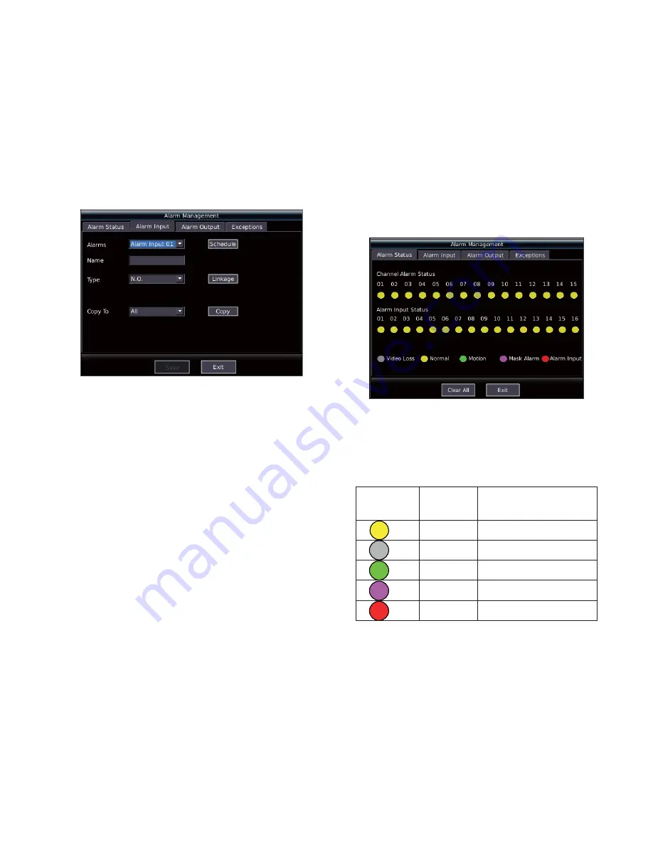
 

4.5.2 Alarm Input 

The DVR supports 16 channels alarm input. Each input can set 
schedule time, alarm name, alarm type and linkage separately. 
Enter the "Alarm" menu interface, and switch to Alarm input" 
option to enter the alarm input setting interface via 

Ǐ

WIDE

ǐ

key, as 

shown in Figure 4-10. 


Figure 4-10 


1. Select alarm inpu

Move the cursor to the alarm input, set a corresponding alarm input 
number, and set the alarm type. The default setting is normal open. 

2. Set Schedule 

Refer to "(3) Set schedule" of "Video mask alarm" in section 4.5.1. 

3. Set alarm linkage 

Refer to "(6) Set alarm linkage" of "Video motion detection" in 
section 4.5.1. 

4. Copy and save 

Select the drop-down list of "Copy to", and press

Ǐ

ENT

ǐ

key. Select 

the target channel, and move the cursor to "Copy" button, press 

Ǐ

ENT

ǐ

key to o copy the current parameters setting temporarily, 

then move the cursor to "Save" button, and press

Ǐ

ENT

ǐ

key to copy 

the parameters to other channels. Exit the menu without save, the 
copy of parameters is not successful. 
After the settings above, alarm linkage will activate when there's 
alarm input. 
 

4.5.3 Abnormity Alarm 

Abnormity alarm includes hard disk full, hard disk error, network 
cable disconnected, unauthorized access and network conflict 
alarms. Users can response quickly to system abnormities with the 
help of abnormity alarm. 

1. Select alarm type 

Move the cursor to "Type" of abnormity alarm, and press

Ǐ

ENT

ǐ

key 

to drop down the list, and select corresponding alarm type. 

2. Output setting 

Move the cursor to the output check box, and press

Ǐ

ENT

ǐ

key, the 

status becomes "

9

". Refer to "Set alarm output" of "Video mask 

alarm" in section 4.5.1 for the setting of "audible warning", "control 
center" and "Trigger alarm output". 

3. Copy and save 

After finishing setting, move the cursor to "Copy", and press 

Ǐ

ENT

ǐ

key to copy the current parameter setting temporarily, then 

move the cursor to "Save" button, and press

Ǐ

ENT

ǐ

key to copy the 

parameters to other channels. Exit the menu without save, the copy 
of parameters is not successful. 
 

4.6 Alarm Management 

1. Alarm status 

After enter "Alarm management" menu, enter "Alarm status" menu 
directly, as shown in Figure 4-11. 


Figure 4-11 


Note

: The interface shows all 16 channels alarm status and alarm 

input status. The different icon of each channel indicates the status, 
as follows: 

Table 1 Icon introduction for alarm status indicators 

Indicator 

Icon

Color Status 


Yellow 

Normal (No alarm) 

 Gray 

Video 

loss 

 Green 

Motion 

detection 

 Rosered Video 

mask 

 Red 

Alarm 

input 

2. Alarm handling 

(1) 

Clear a single alarm 

Follow the following method to clear the alarm when there's alarm: 
Move the cursor to the channel indicator that need to clear the 
alarm, then the indicator will turn off, and press

Ǐ

ENT

ǐ

key to clear 

the alarm in that channel. 
(2) Clear all alarms 
In the alarm management menu, move the cursor to "Clear All" 
button, and press

Ǐ

ENT

ǐ

key to clear all alarms. 


Summary of Contents for V3061 Series

Page 1: ...1 series Embedded Network Digital Video Recorders V3061 series DVR employs high performance power PC hardware structure embedded Linux system and dual 1000M network port design to provide an excellent...

Page 2: ......

Page 3: ...o Recorders all comply with Part 15 of the FCC rules Operation is subject to the following two conditions y This device may not cause harmful interference y This device must accept any interference re...

Page 4: ...away from ground and access way z Refer all service matters to qualified personnel z Save product packaging to ensure availability of proper shipping containers for future transportation Indicates tha...

Page 5: ...id or metal on DVR which may cause short circuit even fire inside DVR z Install the harddisk correctly before use or else you can t make any record operation z The dust of the mainboard may cause shor...

Page 6: ......

Page 7: ...DVR 14 4 2 User login and Authority 14 4 2 1 User login 14 4 2 2 User Authority 15 4 3 Preview 15 4 3 1 Switch preview modes 15 4 3 2 Preview setting 15 4 4 PTZ control 15 4 4 1 PTZ parameters setting...

Page 8: ......

Page 9: ...ontrol protocols of leading encoders support preset and pattern y Support zoom in function by mouse operation when control Infinova second generation domes y 8 SATA hard disks supported maximum 2TB fo...

Page 10: ...ting receiving data 3 STATUS Status indicator Green DVR is being controlled by remote controller Red DVR is in PTZ control status Orange DVR is in PTZ control status and is being controlled by remote...

Page 11: ...splay lower status bar in preview interface TELE Control key Zoom in in PTZ control PTZ Control key 1 Quick enter to PTZ control mode 2 Close iris in PTZ control same as IRIS key Direction keys Contro...

Page 12: ...1 Switch among input methods numeral English and symbol 2 Set the full screen as setting area in Mask Video mask alarm Motion detection setting 6 SYS System Information Function key The function is t...

Page 13: ...e number should be 1 127 3 Stop using remote controller Press DEV key when the DVR is being controlled the status indicator will turn off and then the remote controller stops to control the DVR 4 Shut...

Page 14: ...recording parameters 2 Installation Tool One Philips head screw driver 3 Install Hard Disk 1 Open the housing 2 Install the hard disk 8 interfaces are available for V3061 DVR 3 Remove the hard disk ra...

Page 15: ...lay device for video output and menu display 8 ETHERNET PORT 2 10 100 1000Mbps self adaptive Ethernet port for connection network device RJ45 connector 9 RS 232 INTERFACE Connect with RS 232 serial de...

Page 16: ...Indicator J901 1 G 5V Alarm Circuit Figure 2 5 Alarm output AC load connection DVR Alarm Output Port AC or DC Load J901 1 G 5V Alarm Circuit Relay DC AC Figure 2 6 Alarm output relay connection As sho...

Page 17: ...wisted cable 8 cores one standard RJ45 connector one or more DB25 or DB9 plug a special tool for RJ45 one soldering iron and some solder 2 Pin definition Refer to Figure2 7 for the pin sequence of RJ4...

Page 18: ...GND Serial Port Connection Cable DB9 Female Type Device Figure 2 17 RJ45 and DB9 female type device connection 4 When the RJ45 serial port of the DVR is connected with the device with DB9 male type co...

Page 19: ...3 3 Every menu has many operations below section will have detailed introduction on operation of common use control and input method 3 1 1 Cursor Switching The cursor can be switched via WIDE and key...

Page 20: ...t menu Unselect All Cancel the selection of the options in current menu Search Search the content match with the setting Refresh list Refresh the data in the list Play Play the file selected in the cu...

Page 21: ...put Audible Warning Control Center Alarm Preview and 4 Alarm Outputs Channel Advanced Settings Video Sensitivity Area Schedule Week Time Motion Detection Linkage Recording PTZ control Audible Warning...

Page 22: ...Main Functions Introduction 4 1 Turn on DVR Note The DVR supports 100V 240V self adaptive power supply Before powering on please confirm the AC voltage matches with the requirements of the DVR and mak...

Page 23: ...ey to turn on the recording status list 3 Playback press PLAY key to turn on play interface 4 PTZ control press PTZ key to start the PTZ control From keys combination user can enter and switch among d...

Page 24: ...be a login window if the operation password is enabled Login with the user name that has the authority to perform PTZ control and correct password and then control the direction movement by and keys Q...

Page 25: ...st to select the desired channel and press ENT key to confirm the selection Select the video mask option and press ENT key to enable it and allow mask alarm setting sensitivity area schedule time link...

Page 26: ...Set alarm output Refer to 4 Set alarm output of Video mask alarm in section 4 5 1 5 Copy and save Refer to 5 Save of Video mask alarm in section 4 5 1 3 Motion detection alarm 1 Select channel Refer t...

Page 27: ...quickly to system abnormities with the help of abnormity alarm 1 Select alarm type Move the cursor to Type of abnormity alarm and press ENT key to drop down the list and select corresponding alarm ty...

Page 28: ...he DVR will keep on recording Since the priority of alarm recording is higher the manual recording will stop when the channel is in the alarm recording status The manual recording resumes after finish...

Page 29: ...rent settings temporarily then move the cursor to Save button and press ENT key to copy the parameters to other channels Exit the menu without save the copy of parameters is not successful 4 7 3 Alarm...

Page 30: ...he playback speed It s 1X for normal play The DVR supports 4 slow play speeds 1 2 1 4 1 8 and 1 16 and 4 fast play speeds X2 X4 X8 and X16 3 Functional button instruction Button Instruction Button Ins...

Page 31: ...writer has been installed and the disk is placed in writer before backup Refer to writer installation in section 2 7 Follow the method introduced in section 4 8 3 to select the file to be backup Afte...

Page 32: ...In the preview interface press MENU key to enter the interface as shown in Figure 5 1 Select Preview and press ENT key to enter preview settings interface as shown in Figure 5 2 Press number key 2 al...

Page 33: ...eral settings include 11 settings as follows y NIC y NIC type y IP type y IP address y Subnet mask y Gateway y Mac address y Auto DNS server y DNS server y Routing list y Default gateway The introduct...

Page 34: ...advanced settings include 6 options as follows y Default port y HTTP port y Alarm center y NAS IP y NAS path The introduction of each option as follows 1 Default port The default value is 5000 2 HTTP...

Page 35: ...t user and delete user is displayed in a list box The administrator has authority to perform all functions related to user management 1 View user information In the user management interface select th...

Page 36: ...mote controller introduction in section 1 3 for the operation of controller and V2117 keyboard operation manual for the operation of keyboard 2 Device name The device name supports 1 to 20 characters...

Page 37: ...n operation and preview 2 Minor type The corresponding hypo types of the 5 main types It s convenient for user to search the specific log the operation is the same with major type 3 Time Search the lo...

Page 38: ...the system to default setting if the system run abnormally In the preview mode press MENU key to enter the interface as shown in Figure 5 1 Select System and press ENT key or number key 9 to enter th...

Page 39: ...ick Properties in the Options menu to display the dialog box in the following figure Figure 5 21 3 Click on Playback in the Adjust Volume for click OK to return the volume control dialog box in the fo...

Page 40: ...Infinova 51 Stouts Lane Monmouth Junction NJ 08852 U S A Tel 1 888 685 2002 USA only 1 732 355 9100 Fax 1 732 355 9101 sales infinova com V1 2 1209...

Reviews: