


1 - 26
IP
N 07
4-
46
2-
P1
C
Sion Operating Manual
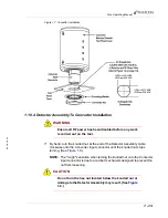
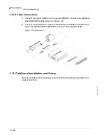
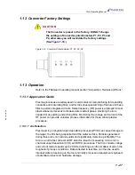
1.10.6 Cable Connections
1
Connect the Signal Cable to the Converter SENSOR I/O jack and a Breakout
Box SENSORS jack as shown by
.
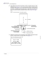
2
Connect the NiDAQ 68 Pin Cable to the NiDAQ PCI 6220M or 6224M board
and to the FABGUARD COMPUTER connector on the Breakout Box.
Figure 1-32 System layout
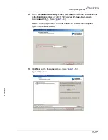
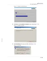
1.11 FabGuard Installation and Setup
Refer to the FabGuard operating manual for FabGuard software installation and
setup instructions.
Summary of Contents for Sion
Page 1: ...O P E R A T I N G M A N U A L Sion RF Detector IPN 074 462 P1C ...
Page 2: ......
Page 6: ......
Page 8: ......
Page 44: ...2 4 IPN 074 462 P1C Sion Operating Manual This page is intentionally blank ...
Page 48: ...3 4 IPN 074 462 P1C Sion Operating Manual This page is intentionally blank ...
Page 50: ...4 2 IPN 074 462 P1C Sion Operating Manual This page is intentionally blank ...
Page 52: ...Index 2 IPN 074 462 P1C Sion Operating Manual This page is intentionally blank ...