


1 - 8
IP
N 07
4-
46
2-
P1
C
Sion Operating Manual
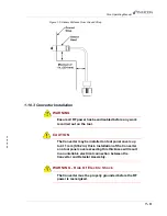
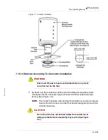
1.10.2 Detector Assembly To RF Strap Installation
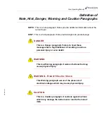
WARNING - Risk Of Electric Shock
Ensure all RF power has been disabled before any work
is carried out on the tool.
1
Remove the tool panel cover to expose the RF transmission strap or rod.
2
Determine where on the RF strap or rod the Detector will be located. Because
the tool panel cover will need to be opened approximately 76 mm (3 in.) to
access the Detector Assembly to Converter connection (see
), the interface between the Detector and RF strap/rod (see
) must be within 203 mm (8 in.) of the Converter mounting hole
(see
). If it is required that the tool panel cover be
opened more than 76 mm (3 in.), the distance between Detector and Converter
must be decreased accordingly.
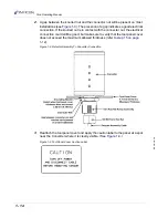
3
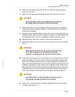
Determine the orientation of the clamp when connecting the Detector Assembly
to the RF strap or rod. (See
.)
4
With the Detector and clamp surrounding the RF strap or rod, insert two thumb
screws through the Detector and then turn the screws into the clamp until finger
tight. (See
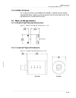
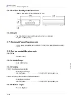
Figure 1-4 Detector Head — Strap and Rod Sizes
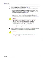
5
If the detector is to be installed on a strap that has a bend causing the strap to
run along the side of the detector, or if the cable must be routed close to high
voltage, the minimum distance between the sensor and cable and any point of
high voltage must be 1 in. (25.4 mm). See
.
Summary of Contents for Sion
Page 1: ...O P E R A T I N G M A N U A L Sion RF Detector IPN 074 462 P1C ...
Page 2: ......
Page 6: ......
Page 8: ......
Page 44: ...2 4 IPN 074 462 P1C Sion Operating Manual This page is intentionally blank ...
Page 48: ...3 4 IPN 074 462 P1C Sion Operating Manual This page is intentionally blank ...
Page 50: ...4 2 IPN 074 462 P1C Sion Operating Manual This page is intentionally blank ...
Page 52: ...Index 2 IPN 074 462 P1C Sion Operating Manual This page is intentionally blank ...