


16
6. Device overview
6.1 Signal indicators
V1.0: If no error is present, then LED Power shows the function control (briefly off).
V4.0 and later: If no error is present, then LED Power shows the operating state (on).
During the output of an error message, the number of output pulses indicates the error:
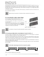
5. System components fitted to the gate
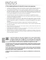
6.2 Connection terminals
Pin 1, 2
Stationary coil core
Pin 3
Supply v24 V DC
Pin 4
GND
Pin 5, 6
Output Stop closing movement
Pin 7, 8
Output Stop opening movement
Pin 9
Test input
Pin 10
No assignment
1 Control device INDUS onboard 70-755
2 Stationary coil core
3 Travelling coil core
4 Steel cable acting as transmission medium
Example of use
The actual arrangement of the individual compo-
nents depends on the design of the gate in question
and the conditions at the installation site.
LED
POWER
green
V1.0: Functional test (off briefly)
V4.0 and later: operating state (on)
Error message (pulse output)
LED
FAULT OPEN
red
Fault, opening movement - travelling safety contact edge(s)
LED
FAULT CLOSE
red
Fault, closing movement - travelling safety contact edge(s)
Pulse
Error message
1
Voltage supply outside of the valid value range
2
inductive signal transmission system error
5
Data transmission with microcontroller faulty
English
2
1 2
P
ower
O
pe
n
Close
I
SK 70-755
2
4
3
Gate opens
Gate closes
safety contact edge
OPEN
movement
safety contact edge
CLOSE
movement
Inductive signal transmission system
LED
Power
LED
Fault Opening
LED
Fault Closing
1
2
3
4
9
8
7
6
5
10
1