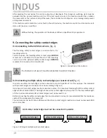
Indus onboard 70-755 Operating Manual Download Page 15

14

15

3. General information and functional description

The compact and easy-to-install safety relay is designed for use on 

controllers that are equipped with the appropriate plug base with 

proper configuration.

The  inductive  signal  transmission  system  solves  the  problem  of 

connecting moveable safety contact edges to a stationary evaluation 

system  without  mechanical  stress.  Communication  between  the 

moveable safety contact edges and the electronic evaluation system 

is  based  on  induction.  To  achieve  this,  the  monitoring  electronics 

induce  a  frequency  on  a  coil  core,  which  is  integrated  in  a  closed 

conductor loop.
The second coil core, to which the moveable safety contact edges 

are  connected,  receives  this  frequency  and  sends  corresponding 

feedback to the electronic evaluation system in the event of cable 

break or actuation of a safety contact edge.
Up to two moveable safety contact edge circuits that travel on the gate leaf can be connected to the switching 

unit. These safety contact edge circuits are monitored by the signal transmission system contact- and wear- 

free.
There are two types of safety contact edge circuits:“safety contact edges - opening movement“ and „safety 

contact edges - closing movement“.
The switching unit continuously monitors these two safety contact edge circuits for actuation or interruption 

(cable break). In the event of a fault, one of the two stop commands (stop in the opening direction or stop in 

the closing direction) is issued to the respective safety contact edge circuit. A terminating resistor is integrated 

into the end edge of the safety contact edge circuit in order to enable the standby current of the entire system 

to be monitored. If the specified standby current is flowing, the open collector outputs relays are activated. If 

a safety edge is actuated or the sensor circuit is interrupted, the respective „open collector outputs“ switch. 

For increased safety, both output channels are fitted with two switching stages. The switching states of the 

open collector outputs and the applied operating voltage are indicated by LEDs.
If an error is present, all the safety outputs are not active.

4. Proper use

The switching unit is intended to be used as protection in combination with safety contact edges with 

integrated 8.2 KΩ resistor for standby-current monitoring on a gate system.

The switching unit can only fulfil its safety-related task if used properly.

Any uses above and beyond these uses constitute improper use. The manufacturer assumes no liability for 

damages arising from improper use.

The device may only be used in special applications with the manufacturer’s express consent.

P

o

w

er

C

lo

se

O

p

en

English

INDUS onboard 70-755

Inductive signal transmission system

Summary of Contents for onboard 70-755

Page 1: ...G ltigkeit siehe letzte Seite INDUS onboard 70 755 Induktives Signal bertragungssystem Seite 3 11 Manuel d utilisation Validit voir la derni re page INDUS onboard 70 755 Syst me de transmission de si...

Page 2: ...suppl mentaires Componenti ausiliari Bijkomende componenten Funktionspr fung Functional test Contr le de fonction Controllo funzionale Functiecontrole Sicherheitssensoren reagieren auf Bet tigung Saf...

Page 3: ...sorgungsspannung 7 8 2 Anschluss feststehender Spulenkern 7 8 3 Anschluss Steuerstromkreise 7 8 4 Anschluss Testsignal 7 8 9 Anschlie en der Sicherheitskontaktleisten 8 9 1 Anschluss am Spulenkern SPK...

Page 4: ...ht aber die Sicherheit der gesamten Anlage Maschine Vor dem Einsatz des Ger tes ist deshalb eine Sicherheitsbetrachtung der gesamten Anlage Maschine nach der Maschinenrichtlinie 2006 42 EG oder nach e...

Page 5: ...ermanent auf Bet tigung oder Unterbrechung Kabelbruch Bei einer St rung wird dem entsprechenden Sicherheitskontaktleistenkreis einer der zwei Stop Befehle zugeordnet Stop in Auf Richtung oder Stop in...

Page 6: ...Fehlermeldung vor so wird ber die LED Power der Betriebszustand angezeigt an Bei Ausgabe einer Fehlermeldung gibt die Anzahl der ausgegebenen Pulse den Fehler an Pulse Fehlermeldung 1 Spannungsversorg...

Page 7: ...f r eine ausreichende Schutzbeschaltung zu sorgen 8 1 Anschluss Versorgungsspannung Als Spannungsversorgung bei dem INDUS onboard 70 755 muss die Steuerung 24 V DC am Steckverbinder Pin 3 und GND am...

Page 8: ...en muss dieser mit einem 8 2 k Widerstand belegt werden Die mitfahrenden Sicherheitskontaktleisten werden mit dem mitfahrenden Spulenkern SPK 54 verbunden Hierzu wird die mitfahrende Sicherheitskontak...

Page 9: ...drahtung und Anlegen der Versorgungsspannung darf nur die gr ne LED leuchten Liegt ein interner Fehler vor so wird ber die Anzahl der Pulse die Fehlerkennung ausgegeben Bei Aufleuchten der Led FAULT C...

Page 10: ...13159 001 Pr fbericht Nr 12 205 413159 001 13 Technische Daten Kleinspannung UE 24 V DC 10 Leistungsaufnahme PE 1 W Stromaufnahme IE 35 mA Versorgungsspannung Anschlusswiderstand Sicherheitskontaktlei...

Page 11: ...n der nachfolgenden EG Richtlinien und Normen entspricht EG Maschinenrichtlinie 2006 42 EG EN ISO 13849 1 2008 EN ISO 13849 2 2008 EN 61000 6 2 2005 EN 61000 6 3 2007 EG Baumusterpr fung Notified Body...

Page 12: ...12...

Page 13: ...2 Connecting the stationary coil core 17 8 3 Connecting the control circuits 17 8 4 Test signal 17 18 9 Connecting the safety contact edges 18 9 1 Connecting to the SPK 54 coil core 18 9 2 Connecting...

Page 14: ...nt machine must therefore be assessed in accordance with machinery directive 2006 42 EC or appropriate product norm before using the device The operating instructions must always be available at the p...

Page 15: ...ese two safety contact edge circuits for actuation or interruption cable break In the event of a fault one of the two stop commands stop in the opening direction or stop in the closing direction is is...

Page 16: ...as transmission medium Example of use The actual arrangement of the individual compo nentsdependsonthedesignofthegateinquestion and the conditions at the installation site LED POWER green V1 0 Functi...

Page 17: ...adequate protective circuits 8 1 Supply voltage With the INDUS onboard 70 755 the controller must make available 24 V DC at connector pin 3 and GND at connector pin 4 8 2 Connecting the stationary coi...

Page 18: ...e connected to an 8 2 k resistor The travelling safety contact edges are connected to the travelling coil core For this purpose the travelling safety contact edge CLOSING movement is connected to conn...

Page 19: ...ge has been correctly connected If the yellow or red LED illuminates there is an error in the system which can be pinpointed with the aid of the LED If the FAULT CLOSING LED or FAULT OPENING LED illum...

Page 20: ...0 Power consumption PE 1 W Current consumption IE 35 mA Supply voltage Terminal resistance of the safety contact edges nominal value Rnom 8 2 k upper switching point RAO 20 0 k lower switching point R...

Page 21: ...s does the version brought to market by us EC machinery directive 2006 42 EC EN ISO 13849 1 2008 EN ISO 13849 2 2008 EN 61000 6 2 2005 EN 61000 6 3 2007 EC type approval Notified Body 0044 T V NORD CE...

Page 22: ...22...

Page 23: ...n 27 8 2 Raccordement du noyau de bobine stationnaire 27 8 3 Raccordement des circuits de contr le 27 8 4 Signal de test 27 28 9 Raccordement de barre palpeuse 28 9 1 Raccordement au noyau de bobine S...

Page 24: ...reil une valuation de la s curit de l ensemble du syst me de la machine est donc indispensable conform ment la directive sur les machines 2006 42 CE ou la norme de produit correspondante Le mode d emp...

Page 25: ...e de ces deux circuits de barres palpeuses En cas d incident un des deux ordres d arr t arr t d ouverture ou arr t de fermeture est attribu au circuit de barres palpeuses correspondant Afin de permett...

Page 26: ...de bobine fixe Broche 3 alimentation 24 V CC Broche 4 GND Broches 5 6 sortie arr t de fermeture Broches 7 8 sortie arr t d ouverture Broche 9 entr e de test Broche 10 non occup e Impulsions Message d...

Page 27: ...inductifs garantir un circuit de protection suffisant 8 1 Alimentation Pour l alimentation en tension de l INDUS onboard 70 755 la com mande doit mettre disposition 24 V CC sur la broche 3 et GND sur...

Page 28: ...r sistance ne doit pas exc der 500 Si un canal n est pas utilis il doit tre pont avec une r sistance de 8 2 k Les barres palpeuses mobiles sont reli es au noyau de bobine mobile Pour cela le mouvemen...

Page 29: ...et plus tard Si le c blage est correct lors de la mise sous tension seule la LED verte doit briller En pr sence d une erreur interne le nombre d impulsions permet d identifier l erreur Si les LED FAU...

Page 30: ...ssance absorb e PE 1 W courant absorb IE 35 mA Tension d alimentation R sistance terminale de barre palpeuse valeur nominale Rnom 8 2 k valeur sup rieure de commutation RAO 20 0 k valeur inf rieure de...

Page 31: ...la s curit et la sant des directives et normes CE suivantes Directive CE sur les machines 2006 42 CE EN ISO 13849 1 2008 EN ISO 13849 2 2008 EN 61000 6 2 2005 EN 61000 6 3 2007 Examen CE du mod le typ...

Page 32: ...est valable que pour les versions suivantes de V 1 0 V 4 0 12 DB 16 301 Operating Manual Rev 01 Subject to technical modifications No liability can be assumed for errors or misprints This operating ma...

Reviews: