background image

19 of 28

Indesit


Company

Service Manual UK

English

CONTROLS INFORMATION

A single control board located at the back of the machine contains all the circuitry to control the 
machine and interfaces with the programme selector, option buttons and LEDs located on the 
console panel. The control board has an access port to the rear of the machine.

MAIN BOARD PROGRAMMING - For Modules with fixed EEProm

PROGRAMMING (Using EMIT)

This machine can be programmed via the Emit, using a USB lead (Part number C00222800), 
Hardware key (Part number C00115587) & the Memwriter software.

The module will always be supplied 
without a programme when 
supplied as a spare part.

NOTE:

 This board does not have a 

physically replaceable EEProm.

Programming a Main Board

There are a number of ways the 
board can be programmed - some 
of which are not applicable to 
certain markets.

Types of programming:

1.

Handheld Terminal (Not UK)

2.

Emit / Memwriter (UK Indesit 
Service Engineers)

3.

Smart Reader & Smart Card 
(certain areas of UK market) 
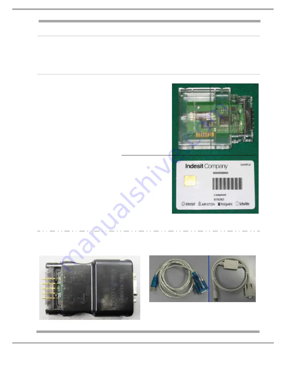
see photo.

Smart Card

Smart Card

this card holds the 
program file and can 
only be used ONCE.

Reader

Black Hardware Key

USB - Serial Cable

A Hardware Key Pin Repair Kit is
available which contains 5 replacement pins
(order Part No. C00114723).

Summary of Contents for SIXL125SEU

Page 1: ...gistered in London 106725 Service Information INDESIT MOON WASHING MACHINES Models Comm Covered Code SIXL125SEU 44033 SIXL145UK 46406 SIXL145SUK 46401 SIXL145DUK 52171 SIXL145DUK 1 55589 SIXL145KUK 60185 SIXL145SKUK 60189 5407359 Issue 6 Nov 2008 Colours may vary ...

Page 2: ...ashers Food Centres etc checks must be made for leaks from seals gaskets and pipe work and rectification carried out where necessary 7 It can be dangerous to attempt DIY repairs maintenance on complex equipment and the Company recommends that any problem with the appliance is referred to its own Service Organisation 8 Whilst the Company has endeavoured to ensure the accuracy of the data within thi...

Page 3: ...on 4 Introduction 5 Installation 6 7 Controls 8 9 Wash Programmes 9 10 Demo Mode 11 Door Dispenser Water Inlet System 12 13 Conductivity Sensor 14 Vent Tube 14 Wiring Diagram 15 Wiring Connection Chart 16 Power Module 17 Eeproms 18 Controls Information Main Board Programming 19 20 Fault Codes LED Indications 21 23 Dismantling Instructions 24 26 ...

Page 4: ... Hz Energy Consumption 1 02 kWh 60 C Maximum Power Consumption 1850W Energy Structure Energy Class A Wash Class A Spin Class B Water Consumption 60 C Cotton 65 litres Water remaining after Spin Cycle 52 Features Full Wash 6 kg Cotton Whites Mixed Coloureds Delicates Rapid 30 minute Rinse only Wash Heater 1700W 230V 30 Ω approximately Water Supply Cold Fill Only Max Pressure 1 Mpa 10bar Minimum Pre...

Page 5: ...s an integral part of the main door assembly and can be removed easily for cleaning replacement by the customer An inner ring of LEDs indicate the programme progress and in the event of a malfunction the LEDs will indicate a Service fault code NOTES The appliance is Cold Fill only Models produced before August 2007 DO NOT have a Demo Mode Models produced from August 2007 have a Demo Mode see Page ...

Page 6: ...iture 2 If the floor is not perfectly level compensate for any unevenness by tightening or loosening the adjustable front feet see figure the angle of inclination measured in relation to the worktop must not exceed 2 Levelling the machine correctly will provide it with stability help to avoid any vibrations and excessive noise and prevent it from shifting while it is operating If it is placed on a...

Page 7: ...ket is able to withstand the maximum power load of the appliance the power supply voltage is falls within the values indicated on the Technical Information page the socket is compatible with the washing machines plug If this is not the case replace the socket or the plug Location The washing machine must not be installed outdoors even in covered areas It is extremely dangerous to leave the applian...

Page 8: ...hine on by pressing the On Off button The symbol on the On Off button lights up and an audible sound will be heard The programme buttons start flashing and the inner ring of LEDs light up one after another At this point the machine is in stand by and is ready for use SELECTING STARTING A PROGRAMME Load the machine with laundry Load detergent and fabric softener Start the required programme by pres...

Page 9: ...e has water in it or not During draining the power on button will flash PROGRAMME PROGRESS The inner ring of LEDs indicates the progress of the wash programme These start to light up in a clockwise direction starting from the LED at the 12 O clock position as more LEDs light up the previous ones remain lit AT THE END OF THE SELECTED PROGRAMME When the wash programme ends the Power On LED and the s...

Page 10: ...press the Delicate programme button again to start the wash cycle which ends with a soft spin 600 rpm Delicates without Final Spin Suitable for garments in silk and viscose curtains Not suitable for Wool garments Press the Delicate programme button After approximately 3 seconds the Delicate and Rapid programme lights begin to flash slowly At this point press the Rapid programme button again to sta...

Page 11: ...ly for approximately 20 30 seconds all of the inner ring of blue progress lights will illuminate and an audible bleep will be heard 3 Demo is now active to commence light sequence press any programme button To De activate Demo Mode 1 Press and hold the ON OFF button to turn machine OFF 2 Hold all 4 programme buttons for approximately 3 4 seconds until a rapid audible bleep is heard 3 Alternatively...

Page 12: ...nt 2 Is for powder detergent 3 Is for fabric conditioner Water Inlet System The machine uses an inlet system designed around two solenoid valves and a dispenser connected by two hoses the appliance will start loading water via solenoid valve 1 but activates the OKO system only with the Cotton 60 C programme During the wash phase water is loaded as follows The washing machine loads water with the f...

Page 13: ...ater is drained for 2 seconds only for the Standard Cotton 60 C The machine finishes loading water with the second solenoid valve 2 through the detergent compartments flushing detergent into the drum During the rinse phase the machine loads water through the fabric conditioner compartment by energising BOTH solenoid valves at the same time 1 1 2 2 2 2 1 ...

Page 14: ...kalinity and calibrate itself The auto setting cycle is repeated every 50 cycles During normal operation the machine will load with water and at this point an alkalinity reading is taken by the sensor software If no alkalinity is detected detergent the machine will activate the standard 30 minute wash cycle If detergent is detected from clothes that have been washed by hand 2 x 15 minute rinse cyc...

Page 15: ...1 2 A 0 1 10w 10w 1A 1A 10A 10A 8A 10A 10A 12A 12A 12A 12A 4 j j2 j14 8 j j3 1 j 5 j D 5 6 R R 6 4 2 1 3 2 1 TG SEN COND RX GND COMUNE PIENO VUOTO 1 9 7 3 4 6 2 3 4 3 2 4 C 1 3 4 2 1 4 3 2 1 2 1 2 1 t s e T R F T R R 5 1 16 1 1 4 1 1 2 1 L N P L EVP EVL OVERFLOWW 1 1 2 2 1 1 2 3 4 5 Stat CP Stat CI t a t S 1 2 3 4 5 6 7 7 6 5 3 2 1 7 6 4 3 1 2 4 5 6a 6a 6a 6a 6a 9 j M T j13 Continuity Sensor Mains...

Page 16: ...BLUE 1 00 X 500 FA4 FA1 1J1 2J1 P16 P11 P14 P12 1J9 2J9 3J9 4J9 5J9 6J9 7J9 8J9 9J9 1J4 2J4 3J4 MRC MRL MRN R TF R R 1J11 2J11 3J11 4J11 5J11 J11 Comunic RST 2 5 EDG PCB 1J15 2J15 3J15 4J15 5J15 4 3 2 1 2 1 1 2 3 1 2 3 4 5 6 7 L N 1J3 2J3 3J3 4J3 5J3 6J3 1J8 3J8 4J8 6J8 7J8 9J8 12J8 EDG RST 5 PCB 11J8 BLUE 1 00 X 940 BROWN 1 00 X 940 RED 0 50 X 1250 BLUE 1 00 X 1250 BROWN 1 00 X 1250 BLUE 1 00 X 1...

Page 17: ...it Company Service Manual UK English POWER MODULE J3 J9 J5 J4 J1 J8 J11 J1 Mains In Live Neutral J3 Pressure Switch Heater J4 Door Lock J5 Conductivity Sensor J8 Wash Valves NTC J9 Motor Pump J11 Display Control Key ...

Page 18: ...tting to the Power Board Eeproms manufactured by ST are used on current production and for spare part requirements EVO2 Eeproms are manufactured by ST These also have a unique identification number as shown Fitting The correct orientation when fitting any version Eeprom is shown below ST 24C64 6 ST 24C64W6 ST 26C64W6P EVO 2 Equivalent Types ...

Page 19: ...key Part number C00115587 the Memwriter software The module will always be supplied without a programme when supplied as a spare part NOTE This board does not have a physically replaceable EEProm Programming a Main Board There are a number of ways the board can be programmed some of which are not applicable to certain markets Types of programming 1 Handheld Terminal Not UK 2 Emit Memwriter UK Inde...

Page 20: ...nserted correctly with the Chip on the card facing the PCB of the Reader 3 Insert the Reader Card into module connection port see photo 4 Connect the machine to the Electrical supply the LED s on the Smart Card Reader will light in this sequence a Red ON Good Communication between Smart Card Reader Card b Red ON Green Blinking Download taking place c At end Green ON Download OK d At end Red ON or ...

Page 21: ... F08 LED 5 LED 4 LED 3 LED 2 LED 1 F09 LED 5 LED 4 LED 3 LED 2 LED 1 F10 LED 5 LED 4 LED 3 LED 2 LED 1 F11 LED 5 LED 4 LED 3 LED 2 LED 1 F12 LED 5 LED 4 LED 3 LED 2 LED 1 5 D E L 7 1 F LED 4 LED 3 LED 2 LED 1 5 D E L 8 1 F LED 4 LED 3 LED 2 LED 1 Motor driving triac short circuit Motor tripped motor tacho generator open or short circuited NTC washing sensor open short circuit Simultaneous empty ov...

Page 22: ...r J8 has secure connections on module Check thermistor and wiring Remove edge connector J8 from module check wiring at position 11 and 12 on connector J8 Remove plug from thermistor The resistance at room temperature 20 C is approximately 20KΩ F04 LED 3 ON Pressure switch stuck on empty Machine continually fills until it reaches overfill safety level Drain pump is then started by overflow contacts...

Page 23: ... and contacts at position 1 2 3 and 4 on pressure switch F11 LEDs 1 2 4 ON Drain pump disconnected Check that the pump connection plug is connected Check edge connector J9 has secure connections on module Remove edge connector J9 on module check wiring and contacts at positions 8 and 9 on connector J9 F12 LEDs 3 4 ON No communication between the display board and the module Check edge connector J1...

Page 24: ...cabinet frame 3 Using a small blade screwdriver remove the programme buttons taking care not to damage or scratch the panel or the buttons Place insulation tape on the cabinet to avoid damage 4 Using the same screwdriver gently prise tabs securing the display PCB to the front E Detergent Dispenser 1 Open the door 2 Pull the detergent dispenser upwards 3 Release the 3 hooks 2 at the front and 1 at ...

Page 25: ... of water 2 Switch the water off lay the appliance on its right hand side to gain access to the sensor 3 Remove the conductivity sensor cable from the sensor 4 Unscrew the conductivity sensor K Mains Cable Suppressor 1 Remove top cover A 2 Remove the screw securing the suppressor and mains cable unit to the cabinet 3 Lift unit upwards and withdraw from the cabinet L Motor 1 Remove the six screws s...

Page 26: ...the cabinet 3 Push the shock absorber on the rod until it comes out of the cabinet 4 Remove the plastic securing bolt from drum and remove shock absorber from cabinet Q Drain Pump 1 Remove the circular plastic cover plate turning anti clockwise 2 Using suitable protection tilt the machine backwards and support 3 Remove the pump fixing screws and disconnect the hoses and wiring R Power Module Repla...

Page 27: ...27 of 28 Indesit Company Service Manual UK English ...

Page 28: ...28 of 28 Indesit Company Service Manual UK English ...

Reviews: