background image


IPX Manual RB01


2.5 

EXTERNAL TRIGGER 

In the
trigge
There
hardw

In ha
the c
optic
signa
exter
volta
signa
TRIG
To li
maxi

uration 

does not affec


determined by

u


ger 

pulse is 100 microseconds. There are no restrictions for the maximum pulse 
duration, but it is recommended that the trigger pulse is kept as short as possible, 
especially if a series of pulses are used. 

In software triggering mode the camera receives the trigger signal coming from 
the frame grabber via camera control signal CC1. In this mode the integration 
time for the first frame is determined by the duration of the actual CC1 trigger 
pulse.  

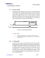
 normal mode of operation, the camera is free running. Using the external 

r mode allows the camera to be synchronized to an external timing pulse. 
 are two general modes available for external triggering – software and 

are.  

rdware triggering mode the camera receives the trigger signal coming from 

onnector located on the back of the camera. The hardware trigger input is 

ally isolated from the rest of the camera hardware - Figure 2.31. The input 

ls “+ TRIGGER IN” and “– TRIGGER IN” are used to connect to an 

nal trigger source. On the edge of the external pulse which creates a positive 
ge difference between “+ TRIGGER IN” and “– TRIGGER IN”, a trigger 

l is sent to the camera. The voltage difference between the trigger inputs “+ 

GER IN” and “– TRIGGER IN” must be positive between 3.3 and 5.0 volts. 

mit the input current a 300 ohm internal resistor is used, but the total 

mum current MUST NOT exceed 25 mA. The actual trigger pulse d

t the integration time. The integration time for th first frame is

 the Pre-Exposure register. The minim m duration of the trig

TO CAMERA

+ TRIGGER IN

- TRIGGER IN

R1
300

25 mA MAX

C A M E R A


 Hardware Trigger Electrical Connection

Figure 2.31 -


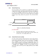
2.5.1 

When the standard triggering mode is enabled, the camera idles and waits 
for a trigger signal. Upon receiving the external trigger signal, the camera 
clears the horizontal and vertical registers, sends one 5 microseconds shutter 
pulse to clear the pixels and starts integration. The exposure time for the 

Standard Triggering - Programmable Exposure  

www.imperx.com


67

 of 

137

     5/6/2005


Summary of Contents for IPX CAMERA SERIES

Page 1: ...CAMERA LINK DIGITAL CAMERAS User s Manual CONFIDENTIAL NOTICE Copyright 2005 Imperx Inc All rights reserved Any unauthorized use duplication or distribution of this document or any part thereof withou...
Page 2: ...IPX Manual RB01 www imperx com Revision History RB01 05 03 05 P Dinev First Release 2 of 137 5 6 2005...

Page 3: ...______________________ 42 2 1 3 Timing Diagrams ________________________________________________ 43 IPX VGA120 IPX VGA210 ____________________________________________ 43 IPX 1M48______________________...

Page 4: ...06 3 8 1 IPX 2M30H Control Registers _____________________________________ 106 3 8 2 IPX 2M30H Video AFE Registers ________________________________ 109 3 8 3 IPX 2M30H Manufacturing Data Registers____...

Page 5: ...anty and Support_____________________________________________ 131 4 1 ORDERING INFORMATION _______________________________________ 132 4 2 TECHNICAL SUPPORT____________________________________________...

Page 6: ...30 Figure 1 12 IPX 2M30 and IPX 2M30H 31 Figure 1 13 IPX 4M15 32 Figure 1 14 IPX 11M5 33 Figure 1 15 IPX VGA 2M30 H 4M15 MDC1600 1920 2048 Top View 34 Figure 1 16 IPX VGA 2M30 H 4M15 MDC1600 1920 2048...

Page 7: ...M48 59 Figure 2 25 Frame Rate vs Vertical Window Size IPX 2M30 60 Figure 2 26 Frame Rate vs Vertical Window Size IPX 4M15 61 Figure 2 27 Frame Rate vs Vertical Window Size IPX 11M5 62 Figure 2 28 Hori...

Page 8: ...a Control 2 Register 85 Table 3 6 IPX VGA External Trigger Duration Register 86 Table 3 7 IPX VGA Vertical Window Top Lines Register 86 Table 3 8 IPX VGA Vertical Window Bottom Lines Register 86 Table...

Page 9: ...28 IPX 1M48 Horizontal Window Size Left Register 94 Table 3 29 IPX 1M48 Horizontal Window Size Right Register 94 Table 3 30a IPX 1M48 AFE Operation Low Register 94 Table 3 30b IPX 1M48 AFE Operation...

Page 10: ...lamp High Register 103 Table 3 49a IPX 2M30 AFE Gain Low Register 104 Table 3 49b IPX 2M30 AFE Gain High Register 104 Table 3 50 IPX 2M30 Manufacturing Data Registers 105 Table 3 51 IPX 2M30H Boot Con...

Page 11: ...5 Table 3 73a IPX 4M15 Shutter Time Select Low Register 115 Table 3 73b IPX 4M15 Shutter Time Select High Register 115 Table 3 74a IPX 4M15 Long Integration Time Low Register 115 Table 3 74b IPX 4M15...

Page 12: ...High Register 124 Table 3 91a IPX 11M egister 124 able 3 91b IPX 11M 124 Table 3 92a IPX 11M5 Horizontal Window Size Left Low Register 124 Table 3 92b IPX 11M5 Horizontal Window Size Right Low Registe...

Page 13: ...IPX Manual RB01 www imperx com Chapter 1 Introduction Introduc r outli era tion This chapte nes the key features of the IPX cam 13 of 137 5 6 2005...

Page 14: ...640x480 120fps monochrome IPX VGA120C 640x480 120fps color IPX VGA210 640x480 210fps monochrome IPX VGA210C 640x480 210fps color Mega pixel IPX 1M48 1004x1004 48fps monochrome IPX 1M48C 1004x1004 48f...

Page 15: ...Link interface that includes 8 10 12 bits data transmission with one or two output taps as well as camera control and asynchronous RS232 serial communication interface all on a single cable The camer...

Page 16: ...tion one pixel at a time onto a floating diffusion output node where the transformation from charge to voltage takes place The resultant voltage signal is buffered by a video amplifier and sent to the...

Page 17: ...0 16 Dummy pixels left 12 8 4 4 12 4 Black columns left 24 12 16 28 28 20 Buffer columns left 4 0 4 4 4 16 Active pixels H 640 1004 1600 1920 2048 4000 Buffer columns right 4 0 4 4 4 16 Black columns...

Page 18: ...B01 Figure 1 2 lor Spectral response co quantum efficiency s Measured with the cover glas Fig ectral respon ntum efficie ure 1 3 Sp se UV qua ncy Measured without the cover glass www imperx com 18 of...

Page 19: ...on G 1 0 G 0 45 G 1 0 G 0 45 Black level offset ls per output 256 levels per output 256 leve Video gain 6 to 40 dB per output 6 to 40 dB per output Gain resolution 0 03 s 0 0351 dB step 1024 steps 51...

Page 20: ...1 0 G 0 45 Black level offset 256 levels per output 256 levels per output 256 levels per output Video gain 0 to 36 dB per output 6 to 40 dB per output 6 to 40 dB per output Gain resolution 0 0351 dB s...

Page 21: ...n G 1 0 G 0 45 G 1 0 G 0 45 Black level offset 256 levels per output 256 levels per output Video gain 6 to 40 dB per output 6 to 40 dB per output Gain resolution 0 0351 dB step 1024 steps 0 0351 dB st...

Page 22: ...Serial Number shows camera model and serial number 1 Camera outpu control and seri 2 Power Connector provides power and I O interface 3 Status LED indicates the status of the camera refer to Status L...

Page 23: ...Camera data output is compliant with base Camera Link standard and includes 24 data bits 3 sync signals LVAL FVAL and DVAL 1 reference clock 1 external input trigger CC1 and a bi directional serial i...

Page 24: ...era Link Clock Tx X 3 DS Out ra Link Chan PAIR 5 6 LV Came nel Tx PAIR 5 19 X 3 LVDS Out Camera Link Channel Tx SerTC DS In eiv PAIR 6 7 LV Serial Data Rec er PAIR 6 20 SerTC LVDS In Serial Data Recei...

Page 25: ...DATA 11 Port B3 B3 N C A11 DATA B 12 Port B4 B4 8 B8 DATA 13 Port B5 B5 B9 B9 DATA 14 N Port B6 B6 C B10 DATA 15 Port B7 B7 N C B11 DATA N B0 B0 16 Port C0 C DATA 17 Port C1 N C B1 B1 DATA 18 Port C2...

Page 26: ...Supply 6 12 V Power Input 12 V Power Supply 7 Strobe Out TTL Output Strobe Light Sync Pulse 8 Strobe Out TTL Output Strobe Light Sync Pulse 9 Reserve Do not use 10 Reserve Do not use Table 1 4 Camera...

Page 27: ...rnal trigger input and strobe output The I O interface connector is shown in Figure 1 7 and the corresponding pin mapping in Table 1 5b 1 3 2 4 Figure 1 7 I O Cable Interface Old Connector Pin Signal...

Page 28: ...mounting holes two on each side located towards the front Figures 1 8 and 1 9 show the front and back view of the C mount and F mount cameras respectively Figures 1 10 to 1 14 show the mechanical deta...

Page 29: ...IPX Manual RB01 IPX VGA120 VGA210 Dimensional Drawings Figure 1 10 IPX VGA120 and IPX VGA0210 www imperx com 29 of 137 5 6 2005...

Page 30: ...IPX Manual RB01 IPX 1M48 Dimensional Drawings Figure 1 11 IPX 1M48 www imperx com 30 of 137 5 6 2005...

Page 31: ...IPX Manual RB01 IPX 2M30 IPX 2M30H Dimensional Drawings Figure 1 12 IPX 2M30 and IPX 2M30H www imperx com 31 of 137 5 6 2005...

Page 32: ...IPX Manual RB01 IPX 4M15 Dimensional Drawings Figure 1 13 IPX 4M15 www imperx com 32 of 137 5 6 2005...

Page 33: ...IPX Manual RB01 IPX 11M5 Dimensional Drawings Figure 1 14 IPX 11M5 www imperx com 33 of 137 5 6 2005...

Page 34: ...ocated in the center two 10 32 UNF holes on the top of the camera located towards the back and two 10 32 UNF holes on the bottom located towards the back Figures 1 15 to 1 18 show the etail drawings o...

Page 35: ...IPX Manual RB01 Figure 1 16 IPX VGA 2M30 H 4M15 MDC1600 1920 2048 Bottom View www imperx com 35 of 137 5 6 2005...

Page 36: ...IPX Manual RB01 Figure 1 17 IPX 1M48 and MDC1004 Top View www imperx com 36 of 137 5 6 2005...

Page 37: ...IPX Manual RB01 Figure 1 18 IPX 1M48 and MDC1004 Bottom View www imperx com 37 of 137 5 6 2005...

Page 38: ...erted under the front lens bezel TION NOTE 1 intensity light source such as a eam 2 Avoid foreign particles on The IPX 4M15 and I lenses which have a 46 5 mm back focal distance An F mount lens can be...

Page 39: ...ure ranging from 100 to 650 C CAUTION NOTE 1 Avoid direct exposure to moisture and liquids The camera housing is not hermetically sealed and any exposure to liquids may damage the camera electronics 2...

Page 40: ...IPX Manual RB01 www imperx com Chapter 2 Camera Features Camera Features This chapter discusses the camera s features and their use 40 of 137 5 6 2005...

Page 41: ...top 4 4 4 2 4 10 16 Buffer rows top 4 4 0 4 2 6 8 Active rows V 480 480 1004 1200 1080 2048 2672 Buffer rows bottom 4 4 0 4 2 8 8 Black rows bottom 0 0 0 4 4 0 16 Dummy pixels left 12 12 8 4 4 12 4 B...

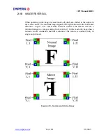
Page 42: ...2 2 In the horizontal direction the first half of the image appears normal and the second half is left right mirrored To reconstruct the norm l image the second half has to be mirrored in the frame gr...

Page 43: ...4 followed by 320 active data pixels Figure 2 4 The data is sampled on the rising edge of the clock and the LVAL line valid signal is active only during the active pixels Each frame for all modes cons...

Page 44: ...ure 2 4 Dual Output Line Timing IPX VGA120 210 DATA FVAL 4 buffer lines TL HB TL 8000 ns dual output TL 16700 ns single output HB 1600 ns 0 0 BL1 0 BL4 0 DL1 DL480 4 buffer lines BL1 0 BL4 0 0 0 RL1 0...

Page 45: ...id signal is active only during the active pixels Each frame for all modes consists of 61 us vertical frame timing followed by 4 masked lines BL1 BL4 followed by 1004 active lines L1 L1004 During each...

Page 46: ...0 L1 L1004 0 DATA 0 0 DL1 DL4 0 0 4 dark lines 1004 active lines TL HB TL 13050 ns dual output TL 25900 ns single output HB 7200 ns gure 2 8 Single Dual Output Frame Timing IPX 1M48 Fi www imperx com...

Page 47: ...s vertical frame timing for single mode 62 us for dual mode followed by 2 masked dark lines RL1 RL2 followed by 4 buffer lines B1 B4 followed by 1200 active lines L1 L1200 followed by 4 buffer lines B...

Page 48: ...HB TL 20600 ns dual output TL 41100 ns single output HB 4000 ns 0 0 0 RL2 0 BL1 0 BL4 0 DL1 DL1200 4 buffer lines BL1 0 BL4 0 0 0 RL1 0 RL4 0 4 dark lines 1200 active lines Figure 2 11 Single Dual Ou...

Page 49: ...onsists of 90 6 us vertical frame timing for single mode 65 9 us for dual mode followed by 4 masked dark lines RL1 RL4 followed by 2 buffer lines B1 B2 followed by 1080 active lines L1 L1080 followed...

Page 50: ...u tput TL 49700 single output HB 00 ns al ou ns 40 0 0 DATA FVAL BL1 0 BL2 0 RL1 0 RL4 0 DL1 DL1080 2 buffer lines BL1 0 BL2 0 0 0 RL1 0 RL4 0 4 dark lines 1080 active lines Figure 2 14 Single Dual Ou...

Page 51: ...ines B1 B8 During each frame the FVAL frame valid signal is active only during the active lines L1 L2048 Figure 2 17 In single followed by 28 masked pixels used for black dark reference R1 R28 followe...

Page 52: ...26700 ns dual output TL 53100 ns single output HB 4000 ns 0 0 BL1 0 BL6 0 DL1 DL2048 8 buffer lines BL1 0 BL8 0 0 0 RL1 0 RL10 0 10 dark lines 2048 active lines Figure 2 17 Single Dual Output Frame T...

Page 53: ...6 During each frame the FVAL signal is active during the active lines L1 L2672 Figure 2 20 In the followed by 20 masked pixels used for black reference R1 R20 followed by 16 buffer pixels B1 B16 follo...

Page 54: ...145571 nssingle output TL 72857 ns single output HB 7142 ns 0 0 BL1 0 BL8 0 RL1 0 RL16 0 DL1 DL2672 8 buffer lines BL1 0 BL8 0 0 0 RL1 0 RL16 0 16 dark lines 2672 active lines Figure 2 20 Single Dual...

Page 55: ...izing a particular area of inte vertical direction is possible by using a vertical window feature Vertical windowing is used for increasing the frame rates For example by skipping half of the lines th...

Page 56: ...er horizontal and vertical resolutions must be adjusted for each window size a The horizontal resolution is equal to the window size which is End Pixel Start Pixel 1 b The vertical resolution is equal...

Page 57: ...for IPX VGA120 and TL is the active line duration TL 18 38 x 10 6 for IPX VGA120 50 100 150 200 250 300 350 400 450 100 200 300 400 500 600 700 800 900 1000 IPX VGA120 FRAME RATE Active Lines Frame Ra...

Page 58: ...l mode and TL L is the active line duration T 18 38 x 10 6 for single mode TL 9 7 x 10 6 ual mode fo 50 100 150 200 250 300 350 400 450 0 500 1000 1500 2000 2500 3000 IPX VGA210 FRAME RATE Active Line...

Page 59: ...de and TL is the active line duration TL 33 1 x 10 6 for single mode and TL 20 3 x 10 6 for dual mode 0 100 200 300 400 0 500 600 700 800 900 1000 2 40 60 80 100 120 140 IPX 1M48 FRAME RATE Active Lin...

Page 60: ...62 x 10 6 for dual mode and TL is the active line duration TL 45 18 x 10 6 for single mode and TL 24 7 x 10 6 for dual mode 0 200 400 600 800 1000 1200 0 50 100 150 200 IPX 2M30 FRAME RATE Active Line...

Page 61: ...for dual mode and TL is the active line duration TL 57 38 x 10 3 for single mode and TL 30 8 x 10 3 for dual mode 0 200 400 600 800 1000 1200 1400 1600 1800 2000 0 20 40 60 80 100 120 IPX 4M15 FRAME R...

Page 62: ...ual mode and T is the active line duration T 152 82 x 10 for single mode and T 80 14 x 10 for dual mode 6 VT L VT VT 6 VT 6 L L 6 L 6 0 500 1000 1500 2000 2500 0 10 20 30 40 50 IPX 11M5 FRAME RATE Act...

Page 63: ...r of 2 and almost doubles the frame rate This occurs because when binning two lines together only half of the lines need to be read out Vertical binning is equivalent to 2 1 sub sampling in the vertic...

Page 64: ...may cause blooming for saturated signal levels 4 alone will lting image will be monochrome ON NOTE Horizontal or vertical binning used alone changes the aspect ratio of the ge in the vertical or horiz...

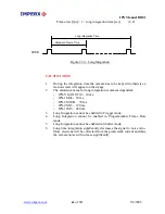
Page 65: ...Shutter Position CAUTION NOTE 1 The electronic shutter can be enabled in all camera modes 2 Position e window will res 2 4 2 Long Integration Long integration is used for extending the image exposure...

Page 66: ...ong Integration cannot be enabled in Trigger mode 4 Long Integration cannot be enabled in Programmable Frame Rate mode 5 Long Integration cannot be enabled in Shutter mode 6 Long time integration sign...

Page 67: ...nput is ally isolated from the rest of the camera hardware Figure 2 31 The input ls TRIGGER IN and TRIGGER IN are used to connect to an nal trigger source On the edge of the external pulse which creat...

Page 68: ...if series of trigger pulses are used make tion refer to section 2 1 4 Timing from 2 msec to 128 msec in 2 msec increments For IPX 11M5 from 5 msec to 320 msec in 5 msec increments There is a fixed ad...

Page 69: ...1 The strobe output can be enabled in all camera modes 2 Positioning the strobe signal outside the frame window will result in error refer to Status LED section 2 6 2 Strobe Electrical Connectivity Th...

Page 70: ...CAMERA STROBE OUT STROBE OUT R2 300 R1 1 0K Q1 2N3904 C A M E R A Figure 2 34 Strobe Output Electrical Connection Internal STROBE ST O R BE 5 0V Strobe Active HIGH 1 2 STROBE OUT BNC STROBE STROBE 5...

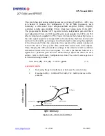
Page 71: ...ts coming out of the CCD there is always some offset misbalance between the video outputs Thus changing the AFE gain leads to a change in the offset level and to a further misbalance between the two v...

Page 72: ...least significant bits are truncated Figure 2 37 12 bit output If the 12 bit original camera data is D0 LSB to D11 MSB and camera is set to output 12 bit data the 12 output bits are mapped to D0 LSB...

Page 73: ...o compensate for this non linearity which is called gamma correction If enabled the video signal is transformed by a non linear function close to the square root function 0 45 power formula 9 1 In the...

Page 74: ...s left right mirrored in the horizontal direction Figure 2 39 This feature could be useful if the camera receives a mirrored image i e image coming from a mirror In this mode the image has a normal ve...

Page 75: ...terns LED uency 0 3 H Long integration mode The e kept steady e smea LED is OFF General error The camera has no power or unexpected er the camera has a green LE s and mode of the back pan h in teady O...

Page 76: ...cal bars for si modes The m tern is gonal gray scale variation sim attern 1 The motion is in the vertical direction The test mode does not exercise and verify the CC ctionality ST MODE mera can output...

Page 77: ...IPX Manual RB01 Chapter 3 Camera Configuration onfiguration igure the camera s operating Camera C This chapter d scusse i s how to conf parameters www imperx com 77 of 137 5 6 2005...

Page 78: ...1 stop bit no pari erates at a rate of 9 600 bps The interfac h the user issuing commands to the camera and the camera either status or info to the user The camera s parame l user terface X series of...

Page 79: ...pace registers from either the factory space or user space as determined by a boot control register located in the configuration memory The b the user refer to Camera Configuration Section The user ca...

Page 80: ...o op s Low Read Write 04 cal in w T Line Vertical Window op es High Read Write 05 T Lin Vertical Wi Read Write 06 ndow Bottom Lines Low Vertical Window Bottom Lines High Read Write 07 Shutter Time Sel...

Page 81: ...Registers Read Write E0 EF EEPROM User Settings Reserved for Future use F0 FE BOOT Boot Control Read Write FF Table 3 1 IPX 1M 8 Camera work space address map 4 R W Address Device Register Ca era Con...

Page 82: ...p High Read Write 25 Gain Low Read Write 26 Gain High Read Write 27 Ch 2 AFE Registers Reserved for Future use 28 2F CCD FP Revision Read Only 30 GA Rese d Future use rve for 31 DSP FPGA Revision Read...

Page 83: ...aracters have to be sent to the cam 8 b reg rit character 0xA5 character register address 3rd character 4th cha ing sequence of characters have to be sent to the camera Please note that the upper and...

Page 84: ...he function uart_send may have different syntax refer to frame grabber manual for the correct function call To prevent the serial buffer from being overwritten after each command a delay of at least 1...

Page 85: ...indow Long Shutter Vertical indow Vertical Mirror Image Dual Out Strobe Table 3 4 IPX VGA Camera Control 1 Register 2 CAMERA CONTROL Address 0x01 factory default value 0x00 D7 D6 D5 D4 D3 D2 D1 D0 8 1...

Page 86: ...0 0 0 0 0 0 0 min 1 1 1 1 1 1 1 1 max Table 3 7 IPX VGA Vertical Window Top Lines Register ERTICAL WINDOW BOTTOM LINES V Address 0x06 factory default value 0xF0 Vertical Window Bottom Lines Low D7 D6...

Page 87: ...PE D4 P 3 E D PE D2 PE D1 PE D0 LIT D9 LIT D8 0 0 0 0 0 0 0 0 min 1 1 1 1 1 1 1 1 max Table 3 10b IPX VGA Pre Exposure Long Integration Time High Register TRO S BE POSITION SELECT Address 0x C factor...

Page 88: ...1 0 0 1 0 0 0 Table 3 14a IPX VGA AFE Operation Low Register AFE OPERATION HIGH Address 0x 11 ch1 0x21 ch2 factory default value 0x00 Operation High D7 D6 D5 D4 D3 D2 D1 D0 0 0 0 0 0 0 0 0 Table 3 14b...

Page 89: ...0 0 0 0 0 0 0 0 0 0 0 0 0 0 0 0 0 0 0 0 0 0 0 0 0 0 Table 3 16b IPX VGA AFE Clamp High Register FE GAIN LOW A Address 0x16 ch1 0x26 ch2 factory default value 0xAA AFE Gain Low D D D D D D D D Value 7...

Page 90: ...00 0xFF B4 ASCII A Z 0 9 B5 ASCII A Z 0 9 B6 A em Number and Revision Number ASCII A Z 0 9 ss bly Part B7 0x00 0xFF HEX B8 0xFF HEX 0x00 B9 Assembly Serial Num r HEX 0x00 0xFF be BA HEX 0x00 0xFF BB H...

Page 91: ...l Binning enable Mirror Image enable Dual Out enable Strobe enable ind enab Lon Integra n e enable S ter Vertical le Window enable Table 3 20 IPX 1M48 Camera Control 1 Register 0 disable 1 enable AMER...

Page 92: ...e 3 23a IPX 1M ica w T Lo ter Tabl 48 Vert l Windo op Lines w Regis ERTICAL WINDOW TOP LINES HIGH V Address 0x05 factory default value 0x00 Vertical Window Top Lines High D7 D6 D6 D5 D4 D3 D2 D1 Valu...

Page 93: ...Time Select Register LONG INTEGRATION TIME LOW Address 0x0A factory default value 0x01 Long Integration Time Low D7 D6 D5 D4 D3 D2 D1 D0 Value 0 0 0 0 0 0 0 0 min 1 1 1 1 1 1 1 1 max Table 3 26a IPX...

Page 94: ...1 1 max Table 3 28 IPX 1M48 Horizontal Window Size Left Register ONTAL WINDOW SIZE RIGHT HORIZ Address 0x0F factory default value 0x01 o Horiz ntal Window Size Right D D D D D D D D Value 7 6 5 4 3 2...

Page 95: ...0 0 0 0 0 0 0 min 1 1 1 1 1 1 1 1 max Table 3 31a IPX 1M48 AFE Gain Low Register AFE GAIN HIGH Address 0x13 ch1 0x23 ch2 factory default value 0x00 AFE Gain High D7 D6 D5 D4 D3 D2 D1 D0 Value 0 0 0 0...

Page 96: ...AFE Clamp High Register AFE CONTROL LOW Address 0x16 ch1 0x26 ch2 factory default value 0x00 AFE Control Low D7 D6 D5 D4 D3 D2 D1 D0 0 0 0 0 0 0 0 0 bl 33 IPX 48 AFE Control Low Register Ta e 3 a 1M A...

Page 97: ...0 0xFF B4 A Z 0 9 ASCII B5 ASCII A Z 0 9 B6 Assembly Part Number A Z 0 9 and Revision Number ASCII B7 HEX 0x00 0xFF B8 HEX 0x00 0xFF B9 Assembly Serial Number HEX 0x00 0xFF BA HEX 0x00 0xFF BB 0x00 0x...

Page 98: ...n enable enable enable enable l enable Strobe enable Shutter enable Vertical Window Vertical Binning Mirror Image Dua Out 0 disable 1 enable Table 3 36 IPX 2M30 Camera Control 1 Register AMERA CONTROL...

Page 99: ...1 1 1 1 1 1 max b a I tical Window Top Lines Low Register Ta le 3 39 PX 2M30 Ver VERTICAL WINDOW LI TOP NES HIGH Address 0x05 factory default value 0x00 Vertical Window Top Lines High D7 D6 D6 D5 D4...

Page 100: ...0 0 0 0 0 0 0 min 1 1 1 1 1 1 1 1 max Table PX h e S R 3 41a I 2M30 S utter Tim elect Low egister H TIM CT HIGH S UTTER E SELE Ad 09 def e 0 Shutter Time Select High dress 0x factory ault valu x00 D7...

Page 101: ...Low D D D D D D D D V 7 6 5 4 3 2 1 0 alue 0 0 0 0 0 0 0 0 min 1 1 1 1 1 1 1 1 max ter Table 3 43a IPX 2M30 Strobe Position Select Low Regis STRO IGH BE POSITION SELECT H Address 0x03 factory default...

Page 102: ...high Horizontal Window Size L R High D7 D6 D5 D4 D3 D2 D1 D0 Value 0 0 0 0 0 0 0 0 min 0 0 0 0 0 0 1 1 0 0 1 1 m x a indow Size Left Right High Register Table 3 45 IPX 2M30 Horizontal W AFE OPE 3 7 2...

Page 103: ...0 0 0 0 0 0 Tabl P 0 AFE Control High Register e 3 47b I X 2M3 AFE CLAMP LOW Address 0x14 ch1 0x24 ch2 factory default value 0x00 AFE Clamp Low D7 D6 D5 D4 D3 D2 D1 D0 Value 0 0 0 0 0 0 0 0 min 1 1 1...

Page 104: ...0 0 0 0 0 0 0 0 min 1 1 1 1 1 1 1 1 max Table 3 49a IPX 2M30 AFE Gain Low Register AFE GAIN HIGH Address 0x17 ch1 0x27 ch2 factory default value 0x00 AFE Gain High D7 D6 D5 D4 D3 D2 D1 D0 Value 0 0 0...

Page 105: ...FF B4 ASCII A Z 0 9 B5 ASCII A Z 0 9 B6 A em Part Number and Revision Number ASCII A Z 0 9 ss bly B7 0x00 0xFF HEX B8 EX 0 H 0x00 xFF B9 A r m x0 0x ssembly Se ial Nu ber HEX 0 0 FF BA HEX 0x00 0xFF B...

Page 106: ...Binning enable Mirror Image enable Dual Out enable Strobe enable ind enab Lon Integr enab n e S ter Vertical le Window enable 0 disable le 1 enab Table 3 52 IPX 2M30H Camera Control 1 Register CAMERA...

Page 107: ...n 1 1 1 1 1 1 1 1 max Table X h e S w Re r 3 55 IP 2M30H S utter Tim elect Lo giste HUTTER TIME SELECT HIGH S Address 0x09 factory default value 0x00 Shutter Time Select High D7 D6 D5 D4 D3 D2 D1 D0 V...

Page 108: ...t Low D D D D D D D D V 7 6 5 4 3 2 1 0 alue 0 0 0 0 0 0 0 0 min 1 1 1 1 1 1 1 1 max Table 3 59a IPX 2M30H Strobe Position Select Low Register ST ROBE POSITION SELECT HIGH Address 0x03 factory default...

Page 109: ...al Window Si e L Hi h D D D D D D D D Value 7 6 5 4 3 2 1 0 0 0 0 0 0 0 0 0 min 0 0 0 0 0 0 1 1 0 0 1 1 max Table 3 61 IPX 2M30H Horizontal Window Size Left Right High Register deo AFE Registers AFE O...

Page 110: ...0 0 0 0 0 0 Table 3 63b IPX 30H AFE Control High Register 2M AFE CLAMP LOW Add 4 h2 factory default value 0x00 E am Lo ress 0x1 ch1 0x24 c AF Cl p w D7 D6 D5 D4 D3 D2 D1 D0 Value 0 0 0 0 0 0 0 0 min...

Page 111: ...0 0 0 0 0 0 0 min 1 1 1 1 max 1 1 1 1 Table 3 65a IPX 2M30H AFE Gain Low Register AFE GAIN HIGH Address 0x17 ch1 0x27 ch2 factory default value 0x00 AFE Gain High D7 D6 D5 D4 D3 D2 D1 D0 Value 0 0 0...

Page 112: ...B4 ASCII A Z 0 9 B5 ASCII A Z 0 9 B6 ASCII A Z 0 9 Assembly Part Nu and m Number ber Revision B7 HEX 0x00 0xFF B8 0x00 0xFF HEX B9 0xFF Assembly Serial Number HEX 0x00 BA 0x0 0x HEX 0 FF BB HEX 0x00...

Page 113: ...on enable enable enable enable l enable Strobe enable Shutter enable Vertical Window Vertical Binning Mirror Image Dua Out Table 3 68 IPX 4M15 Camera Control 1 Register CAMERA CONTROL 2 Address 0x01 f...

Page 114: ...1 1 1 1 1 max indow Top Lines Low Register Table 3 71a IPX 4M15 Vertical W VERTICAL WINDOW LI TOP NES HIGH Address 0x05 factory default value 0x00 ical W o s H Vert indow T p Line igh D 6 D D4 D e 7 D...

Page 115: ...0 0 0 0 0 0 0 min 1 1 1 1 1 1 1 1 max Table PX h e S R 3 73a I 4M15 S utter Tim elect Low egister H TIM CT HIGH S UTTER E SELE Ad 09 def e 0 Shutter Time Select High dress 0x factory ault valu x00 D7...

Page 116: ...ion Sel ct Low D D D D D D D D V 7 6 5 4 3 2 1 0 alue 0 0 0 0 0 0 0 0 min 1 1 1 1 1 1 1 1 max Table 3 75a IPX 4M15 Strobe Position Select Low Register ST ROBE POSITION SELECT HIGH Address 0x03 factory...

Page 117: ...zontal Window Si e L Hi h D7 D6 D5 D4 D3 D2 D1 D0 Value 0 0 0 0 0 0 0 0 min 0 0 0 0 0 0 1 1 0 0 1 1 max Table 3 77 IPX 4M15 Horizontal Window Size Left Right High Register d AFE OPER I L W 3 9 2 IPX 4...

Page 118: ...0 0 0 0 0 Table 3 79b IPX M15 AFE Control High Register 4 AFE CLAMP LOW Add 0x14 0 ch2 factory default value 0x00 E am Lo ress ch1 x24 AF Cl p w D7 D6 D5 D4 D3 D2 D1 D0 Value 0 0 0 0 0 0 0 0 min 1 1...

Page 119: ...0 0 0 0 0 0 0 0 min 1 1 1 1 1 1 1 1 max Table 3 81a IPX 4M15 AFE Gain Low Register AFE GAIN HIGH Address 0x17 ch1 0x27 ch2 factory default value 0x00 AFE Gain High D7 D6 D5 D4 D3 D2 D1 D0 Value 0 0 0...

Page 120: ...3 0xFF HEX 0x00 B4 ASCII A Z 0 9 B5 ASCII A Z 0 9 B6 i m ASCII Number a v nd n Re Nu sio ber A Z 0 9 B7 HEX 0x00 0xFF B8 HEX 0x00 0xFF B9 Assembly Serial 0x00 0xFF Number HEX BA HEX 0x00 0xFF BB HEX 0...

Page 121: ...tion enable enable enable enable l enable Strobe enable Shutter enable Vertical Window Vertical Binning Mirror Image Dua Out Table 3 84 IPX 11M5 Camera Control 1 Register CAMERA CONTROL 2 Address 0x01...

Page 122: ...1 1 1 1 max indow Top Lines Low Register Table 3 87a IPX 11M5 Vertical W VERTICAL WINDOW LI TOP NES HIGH Address 0x05 factory default value 0x00 ical W o s H Vert indow T p Line igh D 6 D D4 D e 7 D 6...

Page 123: ...Value 0 0 0 0 0 0 0 0 min 1 1 1 1 1 1 1 1 max Table 3 9a IPX 11M5 Shutter Time Select Low Register ELECT HIGH SHUTTER TIME S Address 0x09 factory default value 0x00 e Select High Shutter Tim D7 D6 D5...

Page 124: ...robe Position Select Low D7 D6 D5 D4 D3 D2 D1 D0 Value 0 0 0 0 0 0 0 0 min 1 1 1 1 1 1 1 1 max Table 3 91a IPX 11M5 Strobe Position Select Low Register STROBE POSITION SELECT HIGH Address 0x03 factory...

Page 125: ...ght high Horizontal Window Size L R High D7 D6 D5 D4 D3 D2 D1 D0 Value 0 0 0 0 0 0 0 0 min 0 0 0 0 0 0 1 1 0 0 1 1 max Table 3 93 IPX 11M5 Horizontal Window Size Left Right High Register 3 10 2 IPX 11...

Page 126: ...0 0 0 0 0 0 Table 3 95b IPX 11M5 AFE Control High Register AFE CLAMP LOW Address 0x14 ch1 0x24 ch2 factory default value 0x00 AFE Clamp Low D7 D6 D5 D4 D3 D2 D1 D0 Value 0 0 0 0 0 0 0 0 min 1 1 1 1 1...

Page 127: ...0 0 0 0 0 0 0 0 min 1 1 1 1 1 1 1 1 max Table 3 97a IPX 11M5 AFE Gain Low Register AFE GAIN HIGH Address 0x17 ch1 0x27 ch2 factory default value 0x00 AFE Gain High D7 D6 D5 D4 D3 D2 D1 D0 Value 0 0 0...

Page 128: ...0 0xFF B4 ASCII A Z 0 9 B5 ASCII A Z 0 9 B6 Assembly Part Number and Revision Number ASCII A Z 0 9 B7 HEX 0x00 0xFF B8 HEX 0x00 0xFF B9 Assembl Serial Number y HEX 0x00 0xFF BA HEX 0x00 0xFF BB HEX 0x...

Page 129: ...ention per the Camera link specification For each file that it finds it will open the DLL and determine how many ports the DLL supports It will then communicate with each port and attempt to query the...

Page 130: ...is very intuitive and self explanatory The configuration utility includes an interactive help file I controls and camera settings utility dialog will appear The graphical user inte which will guide y...

Page 131: ...IPX Manual RB01 This chapter discusses the camera s warranty and support Chapter 4 Warranty and Support IPX Warranty and Support www imperx com 131 of 137 5 6 2005...

Page 132: ...TION Ordering IPX 11M5 C F Sensor Type Lens Mount M Monochrome C Color U UV sensitive no glass S Special user filter C C mount F F mount O Open frame Camera Model VGA120 VGA210 1M48 2M30 2M30H 4M15 11...

Page 133: ...tus LED and verify that is steady ON if not refer to the LED section 3 Enable the test mode and verify that the communication between the frame grabber and the camera is established If the test patter...

Page 134: ...een open or tampered IMPORTANT NOTICE This camera has been tested and complies with the limits of Class A digital device pursuant to part 15 of the FCC rules Imperx reserves the right to make changes...

Page 135: ...IPX Manual RB01 www imperx com 135 of 137 5 6 2005 Appendix A Software Installation Software Installation This appendix explains how to install the IPX software...

Page 136: ...rX IPX Doc IPX_Users_Manual pdf A 2 Software Installation from CD Use the following steps to install the IPX software supplied on a CD 1 If a version of IPX was previously installed on this machine th...

Page 137: ...added to the IPX camera You can retrieve these updates by visiting the download page of our web site at HThttp www imperx com downloads aspTH 1 Use the following steps to install newly released applic...

Reviews: