background image


Page 

29 of 65


Icon Bar   

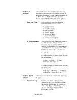
The Icon bar contains a set of icons that act as shortcuts into the features  
located on the Menu bar. 


Start/stop continuous 

Grab 


Snap

 single frame 


Start/stop 

Capture

 to disk


Open 

Camera Parameters

 dialog 


Open 

Color Space Converter

 dialog


Open 

RGB Control

 dialog 


Open 

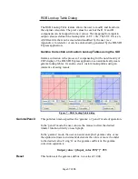
RGB Lookup Table

 dialog


Open 

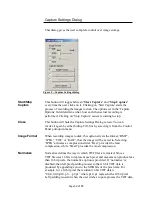
Capture Settings

 dialog


Open 

Statistics

 dialog


Open 

Hex Pixel Dump 

dialog


Open 

Histogram 

dialog


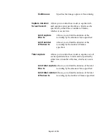
Zoom In 


Zoom Out 


Fit to Window 


Zoom 1:1 


Turn 

Grid

 on/off


Help 


Summary of Contents for HD-SDI Express VCE-HDEX02

Page 1: ...FIDENTIAL PROPRIETARY Page 1 of 65 HD SDI ExpressTM User s Manual CONFIDENTIAL NOTICE Copyright 2008 Imperx Inc All rights reserved Any unauthorized use duplication or distribution of this document or...

Page 2: ...RA03 Mar 12 2009 J Egri Added Unity button to RGB Control dialog RA04 Dec 16 2009 J Egri Updated Table 1 YCrCb 20 bit mode pixel packing RA05 Mar 26 2012 J Egri Added audio support RA06 Jan 22 2013 J...

Page 3: ...EXPRESS APPLICATION 26 MAIN WINDOW 27 CAMERA PARAMETERS DIALOG 31 COLOR SPACE CONVERTER DIALOG 34 RGB CONTROL DIALOG 36 RGB LOOKUP TABLE DIALOG 37 CAPTURE SETTINGS DIALOG 39 HEX PIXEL DUMP WINDOW 50...

Page 4: ...atistics dialog 49 Figure 14 Sample image with Hex Dump region 51 Figure 15 Hex Dump for YCrCb 20 mode 52 Figure 16 Hex Dump for RGB 24 mode 52 Figure 17 Histogram window 53 Figure 18 Zoom menu 54 Fig...

Page 5: ...Page 5 of 65 Chapter 1 Introduction Introduction This chapter outlines the key features of the Imperx HD SDI Express series of SDI frame grabbers VCE HDEX02 VCE HDEX03 VCE HDPCIe01...

Page 6: ...format 4 2 2 YCrCb where Y 10 bits and C 10 bits Captures video data from an SDI analog interface formats this data and stores it into local FIFOs Data can be formatted as 20 or 16 bit YCrCb 4 2 2 or...

Page 7: ...d Electromechanical Specification revision 2 0 The HD SDI Express 54 and HD SDI Express 34 cards comply with the ExpressCard 54 and ExpressCard 34 package dimensions respectively as defined in the Exp...

Page 8: ...ring an attached camera The UART transmits and receives ASYNC formatted characters with 1 Start bit 8 data bits no parity and 1 Stop bit The baud rate of this interface can be configured by the user t...

Page 9: ...sCard Connector Y 10 10 3 C Strobes RxClk JTAG ByteBlaster Programming Header PCI Express PHY TxD TxCLK RxCLK 8 8 RxD TxStrobes RxStrobes TxD RxD 2 CLK 2 2 2 5V to 1 25V converter 1 2V 2 5V 1 25V 3 3V...

Page 10: ...Cr4 Cr3 Cr2 Cr1 Cr0 Y9 Y8 Y7 Y6 Y5 Y4 Y3 Y2 Y1 Y0 Cb9 Cb8 Cb7 Cb6 Cb5 Cb4 Cb3 Cb2 20 bit DW2 Cr1 Cr0 Y9 Y8 Y7 Y6 Y5 Y4 Y3 Y2 Y1 Y0 Cb9 Cb8 Cb7 Cb6 Cb5 Cb4 Cb3 Cb2 Cb1 Cb0 Y9 Y8 Y7 Y6 Y5 Y4 Y3 Y2 Y1 Y0...

Page 11: ...onverter This module is responsible for receiving YCrCb 4 4 4 video pixel data from the chroma_resampler module performing color space conversion and delivering RGB 24 formatted data The following par...

Page 12: ...0 20 R0 19 R0 18 R0 17 R0 16 R0 15 R0 14 R0 13 R0 12 R0 11 R0 10 R0 9 R0 8 DW2 R1 23 R1 22 R1 21 R1 20 R1 19 R1 18 R1 17 R1 16 R1 15 R1 14 R1 13 R1 12 R1 11 R1 10 R1 9 R1 8 R1 7 R1 6 R1 5 R1 4 R1 3 R1...

Page 13: ...ncurrent operation The two FIFOs are utilized in a ping pong fashion such that while one is being filled with new audio data the other is being emptied via DMA into host memory DMA The DMA engines are...

Page 14: ...the following A computer with a PCIe x1 slot or a laptop with an ExpressCard 54 or ExpressCard 34 slot Microsoft Windows Win7 XP Vista 32 or 64 bit operating system software A computer with at least 2...

Page 15: ...package you should visually inspect all of its contents If something is missing or damaged contact your Imperx representative Package contents You should have received the following items The HD SDI E...

Page 16: ...are Installation Hardware Installation Installing the HD SDI Express card is as simple as plugging it into an available PCIe x1 slot on your desktop computer s motherboard or a ExpressCard 54 or Expre...

Page 17: ...gram HD SDI_Express chm Help file DrvManager exe Driver Manager utility VCESDI dll HD SDI Express library ippLib dll Intel image processing library IpxLog dll ImperX logging library IpxMisc dll ImperX...

Page 18: ...pdf Technical datasheet Quick Start HD SDI_Express pdf Quick start document Third party software support files located in c Program Files ImperX HD SDI Express drivers win32 folder contains binaries...

Page 19: ...step 1 8 Click on Remove Click Next Click Yes Click Finish 1 8 Click on Yes 1 9 Click on Close 2 After having removed a previous version or if a version of HD SDI Express was NOT previously installed...

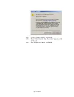
Page 20: ...e software installation 2 7 Reboot your computer The next step is to install the driver files 2 8 Insert the HD SDI Express card into the laptop 2 9 For XP Wait for the system to prompt you with a Fou...

Page 21: ...If this message appears click No not this time then click Next 2 11 When the following message appears select Install the software automatically Recommended then click Next 2 12 The following message...

Page 22: ...Page 22 of 65 2 13 Click Continue Anyway to continue 2 14 When Click finish to close the wizard appears click on Finish 2 15 This completes the driver installation...

Page 23: ...se the following steps to install newly released application software 3 1 Uninstall all application files by following the instructions in step 1 of the Software Installation from CD section 3 2 Downl...

Page 24: ...unzip the firmware Upgrade Utility file to a folder on your PC 2 Insert the HD SDI Express card into the laptop Note that if your system has two ExpressCard slots then you must insert the card into t...

Page 25: ...Page 25 of 65 Chapter 4 Using the HD SDI Express Using the HD SDI Express card This chapter contains information on how to configure and use the HD SDI Express card...

Page 26: ...to view record and playback video data received from the CameraLink interface The application consists of a main window as well as several other dialogs which can be accessed from the main menu or fr...

Page 27: ...ll be automatically scaled as a function of the input signal s parameters i e pixels line and lines frame as reported in the Camera Parameters dialog Figure 3 Main dialog The Main dialog contains a Me...

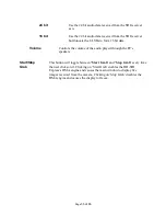
Page 28: ...log to appear Hex Pixel Causes the Hex Pixel Dump dialog to appear Dump Histogram Causes the Histogram dialog to appear Zoom Causes the Zoom menu to appear Help Clicking on this item reveals a pull do...

Page 29: ...tinuous Grab Snap single frame Start stop Capture to disk Open Camera Parameters dialog Open Color Space Converter dialog Open RGB Control dialog Open RGB Lookup Table dialog Open Capture Settings dia...

Page 30: ...If the mode is RGB 24 then the R G and B values will be displayed DMA Displays the real time status of the DMA process as being either Status active or inactive Active indicates that the user has comm...

Page 31: ...ically populated by the application program Format Indicates the format of the connected camera Mode Indicates the mode as Progressive or Interlaced Rate fps Indicates the rate of the connected camera...

Page 32: ...d transfer the video data into host system memory when the mode is interlaced Note that when the mode is progressive then the frames option is automatically selected Frames Interlaced Transfer as a co...

Page 33: ...lume Controls the volume of the audio played through the PC s speakers Start Stop This button will toggle between Start Grab and Stop Grab every time Grab the user clicks on it Clicking on Start Grab...

Page 34: ...data to the RGB 24 format Note that if either the YCrCb 20 or YCrCb 16 mode is selected then YCrCb data is delivered from the card into host memory and therefore the color space conversion function i...

Page 35: ...HD Default Sets all parameters back to the BT 709 default values for HD mode Apply Instructs the color space converter function to use the values entered into the various fields Note that entering val...

Page 36: ...GB Offset Specifies the amount of offset to apply to each of the R G and B components RGB Gain Specifies the amount of gain to apply to each of the R G and B components Unity This button sets all gain...

Page 37: ...ss of compensating for the non linearity of CRT displays The HD SDI Express application can automatically create gamma lookup tables It can also create custom lookup tables using an interactive drawin...

Page 38: ...elect a folder and filename for the current LUT file to be saved The filename extension lut will automatically be added and therefore you do not need to include the filename extension Transfer to card...

Page 39: ...Panel pull down menu Image Format When recording images to disk this option selects the format BMP JPEG TIFF or RAW that the image will be saved in Selecting JPEG activates a compression slider Best p...

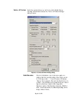
Page 40: ...ption when you wish to record one frame only Clicking on this button causes the Single Frame Settings dialog to open Figure 10 Single Frame Settings dialog Path Filename This text field allows you to...

Page 41: ...enu to appear which defines the placement position of the date time text message within the image Available options include Top Left Top Center Top Right Bottom Left Bottom Center and Bottom Right Acc...

Page 42: ...Filename This text field allows you to provide a path to a folder where the recorded image files will be saved to Clicking on the box will cause a Windows browse box to appear The user can then brows...

Page 43: ...filename starts at 0 and is incremented by one after each frame is captured If the number of frames captured exceeds the number of digits selected then the filename will continue to increment For exa...

Page 44: ...amount of time specified Limit number Allows you to limit the duration of the of frames to recording by the number of frames specified Total capture Allows you to control how much to capture over all...

Page 45: ...apture duration for each event Limit capture time to 00 Hr 05 Min 00 Sec Total capture Limit total number of frames to 250 Example 3 To capture 10 frames every 1 hour over a 6 hour period and not to e...

Page 46: ...ited by the disk s transfer rate Freeze preview When selected will stop the live image in the main window while window from updating during capture otherwise capturing the image will remain live Selec...

Page 47: ...ingle Frames Limit number Allows you to limit the duration of the recording by of frames to the number of frames specified Compressor Allows you to choose between a variety of compressor implementatio...

Page 48: ...Page 48 of 65 Text Overlay Same as in Single Frames Accept Same as in Single Frames Cancel Same as in Single Frames...

Page 49: ...ed into host memory It is the host computer s responsibility to provide the card with pointers into host buffers If the host computer cannot keep up with the incoming frame rate then the card will dro...

Page 50: ...imal and integer values In the RGB 24 sample hex dump see Figure 14 with the mouse positioned at location 1778 508 X Y a box is revealed showing that the value of the R G B components for the pixel at...

Page 51: ...ate X Y of 1767 508 and ending at the lower right pixel coordinate of 1780 509 The yellow square indicates the bounded region The Hex Pixel dumps for the YCrCb 20 and RGB 24 modes are illustrated in F...

Page 52: ...Page 52 of 65 Figure 15 Hex Dump for YCrCb 20 mode Figure 16 Hex Dump for RGB 24 mode...

Page 53: ...R G and B components Each plot is a histogram of the current frame being displayed in the image window as a function of pixel frequency Y axis vs pixel value X axis The pixel frequency in the Y axis r...

Page 54: ...user can change the image window by dragging is sides or corners Note that the Fit to Window function will maintain the aspect ratio of the original image 25 Causes the displayed image to be 25 of th...

Page 55: ...recorded image or movie files that you wish to view Figure 19 Player Control dialog Image Size Determines the size of the Player Dialog window and the playback image Changing from one scale to anothe...

Page 56: ...playing the AVI movie If you are viewing JPEG or BMP images clicking this button displays a series of images one after another starting from the current file selected in the Player Control dialog Step...

Page 57: ...be moved anywhere around the screen to suit your needs The size of the window and image is determined by the size of the image file selected in the Player Control window and can be scaled using the Im...

Page 58: ...Page 58 of 65 Chapter 5 Electrical Interfaces Electrical Interfaces This chapter contains information on the HD SDI Express card s connectors...

Page 59: ...17 CPPE O 1 18 REFCLK I 19 REFCLK I 20 GND 21 PERn0 O 22 PERp0 O 23 GND 24 PETn0 I 25 PETp0 I 26 GND Table 6 ExpressCard Connector Pin out Notes 1 CPPE indicates to the host that the card has been ins...

Page 60: ...WAKE O 2 A11 PERST I 6 B12 reserved A12 GND B13 GND A13 REFCLK I B14 PETp0 I 7 A14 REFCLK I B15 PETn0 I 7 A15 GND B16 GND A16 PERp0 O 7 B17 PRSNT2 O 5 A17 PERn0 O 7 B18 GND A18 GND Table 7 PCIe x1 Con...

Page 61: ...only The COM Port connector is a 6 pin circular Hirose style male jack It includes both RS232 and RS485 interfaces Pin Signal Name Pin Signal Name 1 RS232_Rx 2 RS485 3 RS232_Tx 4 RS485_COM 5 RS232_CO...

Page 62: ...c Formats supported 1080p 30 25 24 fps 1080i 60 50 fps 720p 60 50 30 25 24 fps SD Physical PCIe 84mm x 69mm 3 3 x 2 7 in Dimensions ExpressCard 54 108mm x 54mm x 18mm 4 3 x 2 1 x 7 in ExpressCard 34 1...

Page 63: ...Page 63 of 65 Appendix A Creating Lookup Tables Creating Lookup Tables This appendix provides a reference on how to create a lookup table using both an ASCII editor and an Excel spreadsheet...

Page 64: ...e represents an input value and a set of three output values for R G and B The type of the inputs and outputs is decimal with a range 0 to 255 The input values represent incoming pixels and the output...

Page 65: ...lows 1 create the spreadsheet as shown below note that 256 rows are required in the pixel table 2 add the necessary equations into the output cells to generate the transfer function required 3 save th...

Reviews: