


CAMERAS FRAME GRABBERS IMAGING SOLUTIONS
BOBCAT Hardware User’s Manual
IMPERX
Rev. 2.0.9
6421 Congress Ave.
4/8/2014
Boca Raton, FL 33487
www.imperx.com
+1 (561) 989-0006
65 of 329
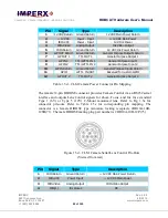
1.4.4 CoaXPress (CXP) Camera Output
The interface between the BOBCAT CXP camera and outside equipment is done via
3 connectors and one LED, located on the back panel of the camera – Figure 1.7.
1.
Camera output – standard BNC provides data, control data, general purpose I/O.
2.
Male 12-pin – provides IRIS, and I/O interface.
3.
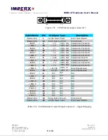
Female 12-pin – provides IRIS, I/O interface with Lens Control outputs.
4.
USB type B programming/SPI connector.
5.
Status LED – indicates the status of the camera – refer to Status LED section.
6.
Serial Number – shows camera model and serial number.
Figure 1.7 – CXP Camera back panel – CoaXPress Output
The Camera’s video data output, control data, triggering, and general I/Os are
serialized and continuously transmitted over CoaXPress (CXP) using single
standard BNC 75 ohm coaxial cable. The interface provides a high-speed downlink
of up to 6.25 Gbps for video transport plus lower speed 20Mbps uplink for
communication and control. Power is also available over the cable and cable lengths
of greater than 100 meters may be achieved.
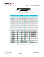
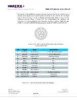
The male 12-pin Hirose connector provides external input/output signals supplied to
the camera. Refer to Fig 1.7a for connector pin-outs. Refer to Table 1.7a for
corresponding pin mapping. The connector is a male HIROSE type miniature
locking receptacle #HR10A-10R-12PB(71). The power supply is shipped with a
power cable which terminates in a female HIROSE plug #HR10A-10P-12S(73), and
has two small BNC pig-tail cables for the external trigger input (black) and strobe
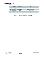
output (white). The corresponding BNC connector pin mapping is shown on Table
1.7b.