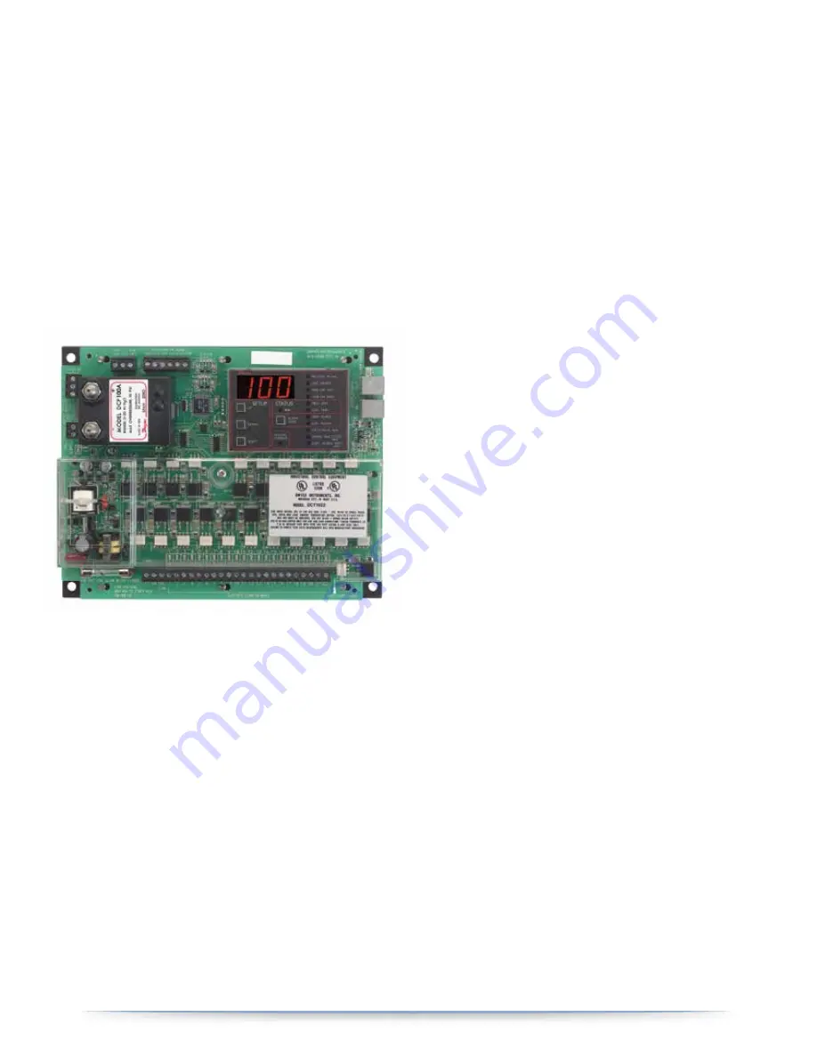
6. DCT1000 CONTROLLER TIMER
The DCT1000 Dust Collector Timer Controller was designed to be used
with pulse-jet type dust collectors for on-demand or continuous
cleaning applications. Continuous cleaning applications do not require
external inputs and can be used for time based “on-demand” cleaning
through use of the cycle delay feature.
For on-demand applications, the plug-in pressure modules (DCP100A)
can be used to take full advantage of all the features the DCT1000 offers,
or an external pressure switch can be used for High/Low limit control.
The Dwyer DCT1000 was designed so that it is easy to use, thus allowing
for a quick and easy start up for your dust control applications.
6.1 PROGRAMMING MASTER CONTROLLER
The menu item that you are currently accessing is indicated by the
illumination of an LED. To change menu items push the “select”, push
“UP” to increase a value or push “DOWN” to decrease a value. The
master controller is equipped with an on board display and
programming information center. The controller will power-up with
the process indicator illuminated. If a pressure module is installed, the
display will indicate the measured pressure in inches of water (w.c.);
otherwise it will normally be blank.
6.1.1 Last Output
The Last Output Setup selects the last channel to be activated. When
first selected, the display will flash the last output available in the
system. With single board installations, this will be the number of
channels installed, typically 6, 10 or 22. This value becomes more
important when multiple modules are installed. The last out-put value
flashed will be the sum of all channels available in the system.
After the last available channel indication has completed, the currently
programmed last channel value is displayed. This value maybe
changed using the “UP” and “DOWN” buttons. The minimum value is
one while the maximum value is the maximum number of installed
channels, including all expansion modules. The default value is the
maximum number of channels. Pressing “SELECT” will change the
setup mode to Time Off Setup.
6.1.2 Time Off (sec)
Time Off Setup defines the period of time between solenoid
activations when no channels are enabled. This may be set between
one second and 255 seconds. The factory default is 10 seconds. The
display will show the current time off setting when the time off setup
mode is entered. The value may be changed using the Up and Down
buttons. Pressing both “UP” and “DOWN” simultaneously and holding
for approximately four seconds will restore the default value of 10.
6.1.3 Time On (msec)
Time On Setup sets the solenoid on time. The display will indicate the
currently programmed time on setting. This is measured in
milliseconds. Using the “UP” and “DOWN” buttons, the value may be
changed. The value may be set between 10 msec and 600 msec in 10
msec increments. Pressing the “UP” and “DOWN” buttons
simultaneously for approximately four seconds will restore the factory
default value of 100 msec. Pressing the “SELECT’ button will advance
the setup mode to the High Limit setup if the pressure module is
installed. With no pressure module, it will step to Cycle Delay Setup.
6.1.4 High Limit (Only With DCP Connected)
The High Limit Setup, available only with a pressure module installed,
sets the pressure at which the cleaning cycle will begin. This value may
be between zero and the pressure module full scale pressure. Normally,
the High Limit should be above the Low Limit. If, however, the High
Limit pressure is set below the Low Limit, the cleaning cycle will begin
when the High Limit is exceeded and stop when the pressure
falls below the High Limit. The Low Limit in this case will have no effect.
Pressing “SELECT” will change the system to the Low Limit Setup mode.
imperialsystemsinc.com
14
Imperial
Systems
Inc.
Summary of Contents for CMAXX
Page 9: ...imperialsystemsinc com 9 Imperial Systems Inc 3 Safety Labels...
Page 24: ...imperialsystemsinc com 24 Imperial Systems Inc 11 ELECTRICAL 11 1 SOLENOID SCHEMATIC...
Page 25: ...imperialsystemsinc com 25 Imperial Systems Inc 11 2 DCT1000 SCHEMATIC...
Page 26: ...imperialsystemsinc com 26 Imperial Systems Inc 11 3 SOLENOID HEATER SCHEMATIC OPTIONAL...
Page 27: ...imperialsystemsinc com 27 Imperial Systems Inc 11 4 INTEGRATED CONTROLS WIRING DIAGRAM...
Page 28: ...MADE IN THE USA 8 0 0 9 1 8 3 0 1 3 i m p e r i a l s y s t e m s i n c c o m...


