HD1-E CANopen instruction manual
- 9 -
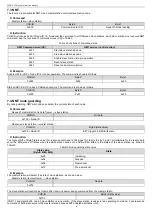
7.5 Heartbeat producer
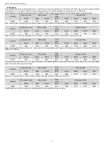
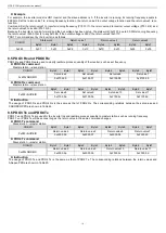
Sometimes, to know the realtime state of the slave station, the master station requires the slave station should automatically send
heartbeat producer every interval defined in object dictionary 0x1017 (16bit data length, unit: ms). If time=0, the slave station will not
send heartbeat producer. The default heartbeat time of HD1-E-COP is 0.
⚫
Command
Slave station
→master station
COB-ID
Byte0
0x700 + Node-ID
State value
⚫
Instruction
The formats for heartbeat producer and node guarding response are the same, but there is no trigger bit alternative variation (always 0)
for heartbeat producer. The state values are shown in Table10.
⚫
Example
For example, when slave station address=3, the slave station is in operation. If the parameter in 0x1017 is set to 100, the slave station
will send a heartbeat producer every 100ms.
COB-ID
Byte0
0x703
0x05
SDO can be used to diable heartbeat producer. Send 2B 17 10 00 00 00 00 00 (time=0).
Note: The same time node guarding and heartbeat producer are not available simultaneously for the communication card.
7.6 NMT boot-up
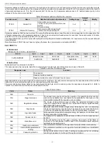
When the communication card finishes boot-up, it will send a start-up message.
⚫
Command
Slave station
→master station
COB-ID
Byte0
0x700 +Node-ID
0x00
⚫
Example
For example, when communication card node=3, the start-up message sent by the communication card after boot-up is shown as
follows:
COB-ID
Byte0
0x703
0x00
7.7 SYNC
Without any data, SYNC signals that CANopen master station usually cycles and sends are mainly used to request the slave station
node to respond process quantity for PDO Tx of synchronous transmission. 0x1005 of object dictionary defines COB-ID that is used to
receive SYNC and connected set to be 0x80. Each PDO Tx 1~240 is synchronous transmission type.
⚫
Command
Master station
→slave station
COB-ID
No data
0x80
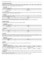
7.8 EMCY
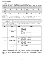
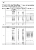
When an error occurs in the communication card or inverter or the error clears, EMCY will be sent.
⚫
Command
Slave station
→master station
COB-ID
Byte0
Byte1
Byte2
Byte3
Byte4
Byte5
Byte6
Byte7
0x80 + Node-ID
Emergency error code
Error register
Inverter error code
LSB
MSB
bit7-0
bit15-8
bit23-16
bit31-24
bit39-32
⚫
Instruction
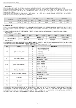
Emergency error code contains two bytes with low Byte0 and high Byte1 while inverter error code consists of five bytes with low Byte3
and high Byte7.
Emergency error code refers to specific current error type, as shown in Table11. EMCY error type can be figured out via current error
type in error register, as shown in Table12.
Refer to inverter manual for inverter error code which is given by function code P07.27 in Appendix2.


