7
STV50 ed 09/08
VICTRIX 50 Rev. 002
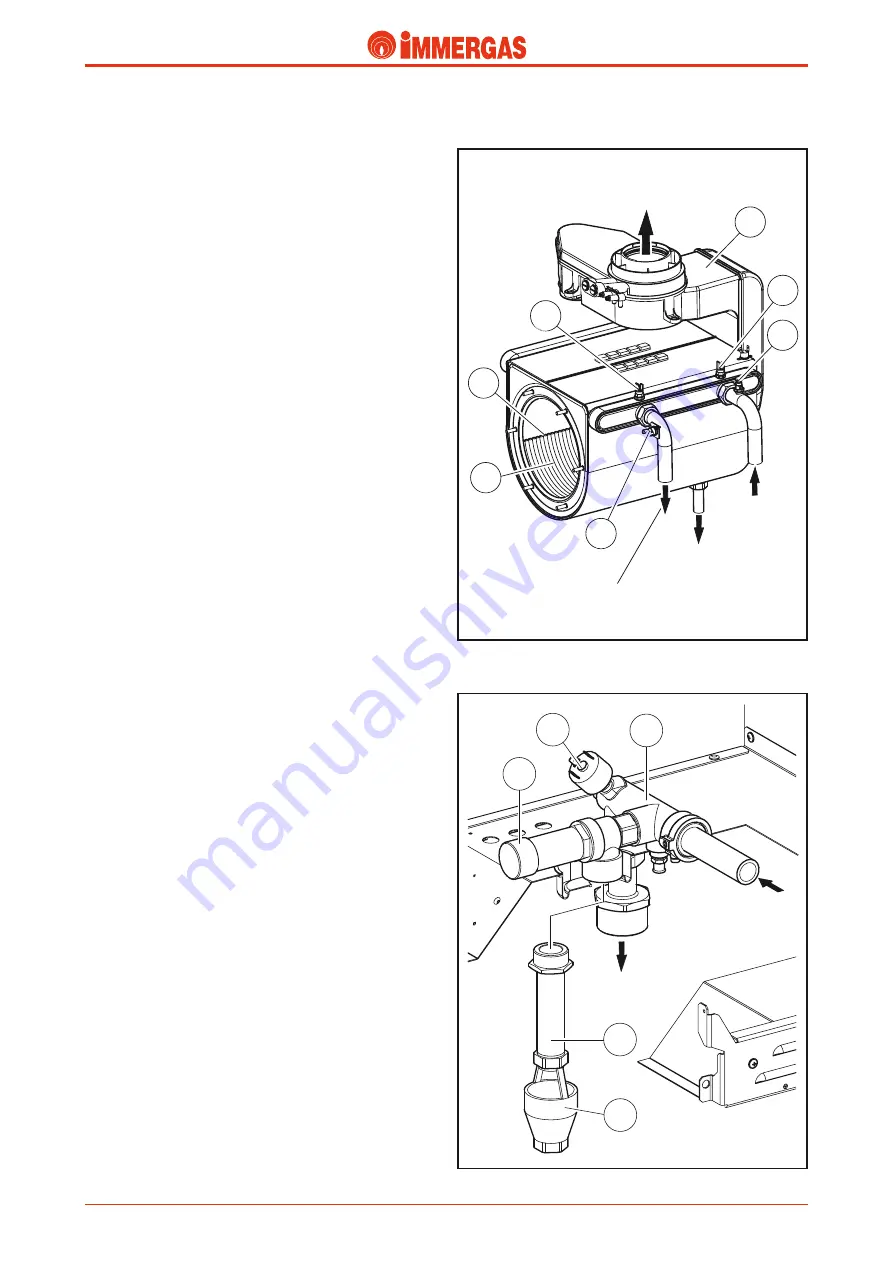
Primary exchanger (condensation module).
It consists of a casing containing 11 coil shaped elements.
Each element is made of 5 elliptic pipe spirals (3).
The whole module is made of stainless steel and the inner part
comprises a sealed combustion chamber and condensation
chamber (2).
The first eight elements are involved directly in the action of the
cylindrical burner, fitted to the front, while the last three are
inside the condensation chamber which is separated from the
combustion chamber by a metal plate
(see the flue circuit)
.
To minimise load losses and increase the flow available for
the system, the delivery consists of the parallel connection of
the first six elements while the return consists of the parallel
connection of the last five elements.
The exchanger inlet is connected to the boiler circulator deliv-
ery on which the system return NTC probe is positioned (5)
while the outlet, on which the system delivery (6) NTC probe
is positioned, is connected to the primary circuit delivery.
Threaded fittings and a flat seal are used to couple the delivery
and return pipes of the primary circuit.
The overheating safety thermostat (1) is installed on the system
delivery pipe.
The draught diverter (4) is connected at the back by means of
a seal locked by a metal ring.
The condensate drain is also found in the lower part.
To ease the escape of any air bubbles still present in the coils,
there is a manual air vent (7) in the upper part of the mod-
ule.
Safety devices and controls.
System pressure switch (2).
This switch detects the pressure inside the primary circuit.
It is housed on the delivery manifold body and coupled to a
microswitch that prevents the burner working when pressure
is below 0.3 bar.
It prevents the main exchanger from overheating.
ISPESL type approved 4 bar safety valve (3).
It prevents the safety pressure from being exceeded in the
circuit (4 bar).
It is located at the front of the delivery manifold body to
which it is coupled.
When this valve trips it causes water to come through the sys-
tem delivery pipe to which an extension pipe (4) is connected
that ends with a collection funnel (5).
5
2
3
4
1
1
4
6
5
2
3
7
System
delivery
System
return
Condensate
discharge
Flue
System
delivery
Technical Documentation
Technical Documentation


