40
STV50 ed 09/08
VICTRIX 50 Rev. 002
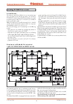
ISPESL safety kit for a single boiler (optional).
With this kit you comply with the ISPESL standards on the
matter of safety in systems with powers higher than 35 kW.
The safety devices and checks consist primarily in an ISPESL
approved thermometer (5), an ISPESL approved manually
reset thermostat (6) and an ISPESL approved manually reset
pressure switch (7).
The contacts of the thermostat (6) and pressure switch (7)
must be installed electrically in series with the boiler’s power
input.
The stub pipes, which are part of the kit, are connected directly
to the boiler’s flow and return pipes with O rings (1).
On the system flow stub pipe it is also possible to mount a
thermometer holder housing device (2) and the probe for the
gas shut-off valve (3). The kit also includes an ISPESL type
approved manometer holder cock element (4) and a ISPESL
approved manometer (12), complete with water hammer
reducing loop (11).
The system return stub pipe, on the other hand, is set for the
connection of an expansion tank that has to be suitable for
system requirements.
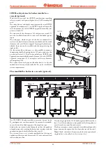
Kit 3-way diverter valve for coupling the exter-
nal storage tank (optional).
With this kit the VICTRIX 50 boiler can be connected - if
wanted - to an external storage tank for the production of
domestic hot water.
The stub pipes in this kit are connected directly to the boiler’s
flow and return pipes with O rings (1).
The 3-way diverter valve (4), with electric motor (5), is installed
on the return stub pipe.
To electrically connect the 3-way diverter valve motor and do-
mestic hot water probe (B2) see the boiler wiring diagram.
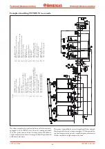
Distribution manifold kit (optional).
With this kit the circulation of water can be increased through
the system, resulting in a more flexible installation even in the
case of big systems or where the water content is very high.
The distribution manifold (2) is connected directly to the
boiler’s flow and return pipes with O rings (1).
A brass filter is installed on the return pipe to collect sludge
(6).
G1"
4
1
5
6
G1"1/2
G1"1/2
1
G1"1/2
G1"
2
A
B
A
B
G1"
G1"
G1"
3
1
2
3
4
5
6
7
G1"1/2
G1"1/2
G1"1/2
G1"1/2
G3/4"
1
10
11
12
Technical Documentation
Technical Documentation


