


7
45
31
58
1-5
1-4
INS
TALL
AT
O
R
US
ER
MAINTEN
AN
CE TECHNI
CI
AN
Position of the central
heating temperature user adjustment
“Comando Amico Remoto”
Remote control
Device
V2
or On/Off chronothermostat elec-
trical connections (Optional).
The operations
described below must be performed after having
removed the voltage from the appliance.
Any
thermostat or On/Off environment chrono-
thermostat must be connected to clamps 40
and 41 eliminating jumper X40 (Fig. 3-2). Make
sure that the On/Off thermostat contact is of
the “clean” type, i.e. independent of the mains
supply, otherwise the electronic adjustment
card would be damaged. Any Comando Amico
Remoto remote control
V2
must be connected to
clamps 40 and 41 eliminating jumper X40 on the
circuit board, paying attention not to invert the
connections (Fig. 3-2).
Important:
if the “Comando Amico Remoto”
remote control
V2
or any other On/Off chrono-
thermostat is used arrange two separate lines in
compliance with current regulations regarding
electrical systems. No boiler pipes must ever be
used to earth the electric system or telephone
lines. Ensure elimination of this risk before mak-
ing the boiler electrical connections.
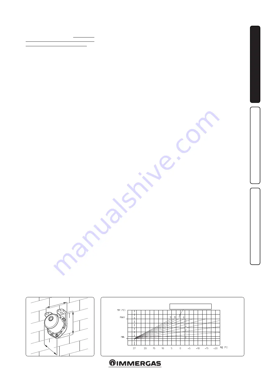
1.7 EXTERNAL PROBE (OPTIONAL).
The boiler is prepared for the application of the
external probe (Fig. 1-4), which is available as
an optional kit.
The probe can be connected directly to the boiler
electrical system and allows the max. system
flow temperature to be automatically decreased
when the external temperature increases, in
order to adjust the heat supplied to the system
according to the change in external temperature.
The external probe always acts when connected
independently from the presence or type of room
thermostat used. The correlation between system
flow temperature and external temperature is de-
termined by the position of the selector switch on
the boiler control panel according to the curves
shown in the diagram (Fig. 1-5). The electric con-
nection of the external probe must be made on
clamps 38 and 39 on the boiler P.C.B. (Fig. 3-2).
1.8 VENTILATION OF THE ROOMS.
In the room in which the boiler is installed it is
necessary that at least as much air flows as that
requested for by normal combustion of the gas
and ventilation of the room. Natural air flow must
take place directly through:
- permanent openings in the walls of the room
to ventilate that lead towards the outside;
- condotti di ventilazione, singoli oppure collet-
tivi ramificati.
The air used for ventilation must be withdrawn
directly from outside, in an area away from sourc-
es of pollution. Natural air flow is also allowed
indirectly by air intake from adjoining rooms. For
further information relative to ventilation of the
rooms follow that envisioned in the regulation.
Evacuation of foul air.
In the rooms where the
gas appliances are installed it may also be neces-
sary, as well as the intake of combustion agent air,
to evacuate foul air, with consequent intake of a
further equal amount of clean air. This must be
realised respecting the provisions of the technical
regulations in force.
1.9 FLUE DUCTS.
The gas appliances with attachment for the flues
discharge pipe must have direct connection to
chimneys or safely efficient flues.
Only if these are missing can the combustion
products be discharged directly to the outside,
as long as the standard regulations for the flue
terminal are respected as well as the existing laws.
Connection to chimneys or flues.
The connec-
tion of the appliances to a chimney or flue takes
place by means of flue ducts.
In the case of connection to pre-existing flues, these
must be perfectly clean as the slag, if present, on
detachment from the walls during functioning,
could obstruct the passage of flue gass, causing
extremely dangerous situations for the user.
The flue ducts must be connected to the chimney
or flue in the same room in which the appliance
is installed or, at most, in the adjoining room
and must comply with the requisites of this
regulation.
1.10 FLUES/CHIMNEYS.
For the appliances with natural draught indi-
vidual chimneys and branched flues can be used.
Individual chimneys.
The internal dimensions
of some types of individual chimneys are con-
tained within the prospects of the regulation. If
the effective system data do not fall within the
conditions of applicability or the table limits, the
size of the chimney must be calculated according
to the regulation.
Branched flues.
In buildings with lots of floors,
branched flues can be used for the natural
draught evacuation of combustion products
(c.c.r.). New CCR must be designed following
the calculation method and regulation standards.
Chimney caps.
The cap is a device positioned
crowning an individual chimney or branched
flue. This device eases the dispersion of combus-
tion products, even in adverse weather condi-
tions, and prevents the deposit of foreign bodies.
This must satisfy the requisites of the regulation.
In order to prevent the formation of counter-
pressures that impede the discharge of combus-
tion products into the atmosphere, the outlet
height corresponding to the top of the chimney/
flue, independently of any caps, must be over the
“backflow area”. It is therefore necessary to use
the minimum heights indicated in the figures
stated in the regulation, depending on the slope
of the roof.
Direct exhaust to the outside.
The natural
draught appliances to be connected to a chimney
or a flue can discharge the combustion products
directly to the outside, through a pipe passing
through the perimeter walls of the building. In
this case discharge takes place through an exhaust
flue, which is connected to a draught terminal
at the outside.
Exhaust flue.
The exhaust flue must be in com-
pliance with the same requisites listed for the
flue ducts, with further provisions stated in the
regulation in force.
Positioning the draught terminals.
The draught
terminals must:
- be installed on external perimeter walls of the
building;
- be positioned according to the minimum dis-
tances specified in current technical standards.
Flue exhaust of forced draught appliances
in closed open-top environments.
In spaces
closed on all sides with open tops (ventilation
pits, courtyards etc.), direct flue gas exhaust is
allowed for natural or forced draught gas ap-
pliances with a heating power range from 4 to
35 kW, provided the conditions as per the current
technical standards are respected.
Important:
it is prohibited to put the flues
exhaust control device out of order voluntarily.
Every piece of this device must be replaced using
original spare parts if they have deteriorated. In
the case of repeated interventions of the flues
exhaust control device, check the flues exhaust
flue and the ventilation of the room in which the
boiler is located.
Summary of Contents for 3.020857
Page 1: ...MINI NIKE X 24 3 E Instruction booklet and warning IE 1 038792ENG...
Page 2: ......
Page 20: ...20 3 5 4 4 5 6 6 d d c INSTALLATOR USER MAINTENANCE TECHNICIAN...
Page 25: ...25...
Page 26: ...26...
Page 27: ...27...


