Immergas 3.020857 Instruction Booklet And Warning Download Page 23

23

INS

TALL

AT

O

R

US

ER

MAINTEN

AN

CE TECHNI

CI

AN

- The data relevant to domestic hot water per-

formance refer to a dynamic inlet pressure of 

2 bar and an inlet temperature of 15°C; the 

values are measured directly at the boiler outlet 

considering that to obtain the data declared 

mixing with cold water is necessary.

- The max. sound level emitted during boiler 

operation is < 55dBA. The sound level value is 

referred to semianechoic chamber tests with 

boiler operating at max. heat output, with 

extension of flue gas exhaust system according 

to product standards.

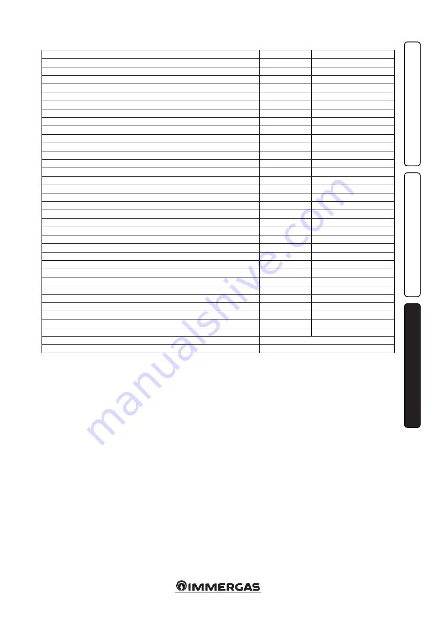
3.20 TECHNICAL DATA.

Nominal heat input

kW (kcal/h)

26.2 (22492)

** DHW minimum heat input

kW (kcal/h)

8.3 (7116)

CH minimum heat input

kW (kcal/h)

10.9 (9357)

Nominal heat output (useful)

kW (kcal/h)

23.8 (20468)

** DHW minimum heat output (useful)

kW (kcal/h)

7.0 (6020)

CH minimum heat output (useful)

kW (kcal/h)

9.4 (8084)

* Efficiency at nominal heat output 

%

91.0

* Efficiency at 30% nominal heat output load

%

89.3

Heat loss at case with burner On/Off

%

2.30 / 1.20

Heat loss at flue with burner On/Off

%

6.70 / 0.09

Central heating circuit max. operating pressure

bar

3

Central heating circuit max. operating temperature

°C

90

Adjustable central heating temperature

°C

35 - 85

System expansion vessel total volume

l

4.0

Expansion vessel factory-set pressure

bar

1

Water content in generator

l

2.5

Total head available with 1000 l/h flow rate

kPa (m H

2

O)

24,52 (2,5)

Hot water production useful heat output

kW (kcal/h)

23.8 (20468)

** Domestic hot water adjustable temperature

°C

10 - 60

** Min. pressure (dynamic) domestic hot water circuit

bar

0.3

** Domestic hot water circuit max. working pressure

bar

10

** Minimum D.H.W. flow rate

l/min

1.5

Drawing capacity in continuous duty with UB Immergas (∆T 30°C)

l/min

11,1

Weight of full boiler

kg

28.0

Weight of empty boiler

kg

25.5

Electrical connection

V/Hz

230/50

Power input

A

0.44

Installed electric power

W

95

Pump consumption

W

87

Equipment electrical system protection

-

IPX4D

Boiler flue circuit resistance

Pa

1.3

NO

X

 class

-

3

Weighted NO

X

mg/kWh

139

Weighted CO

mg/kWh

52

Type of appliance

B11BS

Category

II2H3+

- *Efficiencies refer to the lower heating value.
-  ** When the boiler is connected to an external 

cylinder.

Summary of Contents for 3.020857

Page 1: ...MINI NIKE X 24 3 E Instruction booklet and warning IE 1 038792ENG...

Page 2: ......

Page 3: ...ions specified in the current regulation and technical standards In compliance with legislation in force the systems must be designed by qualified professionals within the dimensional limits establish...

Page 4: ...ting 11 2 7 Boiler shutdown 13 2 8 Restore central heating system pressure 13 2 9 System draining 13 2 10 Anti freeze protection 13 2 11 Case cleaning 13 2 12 Decommissioning 13 3 Boiler start up init...

Page 5: ...e intervenes with an obstructed conveying system the safety valve must be conveyed away by a draining funnel or if there are leaks from the hydraulic connections on the contrary the manufacturer canno...

Page 6: ...order to meet the system requirements es tablished by the technical regulation in force in relation to the pollution of drinking water we recommend installing the IMMERGAS anti backflow kit to be used...

Page 7: ...directly to the outside as long as the standard regulations for the flue terminal are respected as well as the existing laws Connection to chimneys or flues The connec tion of the appliances to a chim...

Page 8: ...started up even if only one of the checks should be negative 1 14 CIRCULATION PUMP The Mini Nike X 24 3 E series boilers are supplied with a built in circulation pump with 3 posi tion electric speed c...

Page 9: ...ystem filling valve 6 Flue safety thermostat 7 Flow probe 8 Primary heat exchanger 9 Safety thermostat 10 Combustion chamber 11 Ignition and detection electrodes 12 System expansion vessel 13 Burner 1...

Page 10: ...is also prohibited in the same room as suction devices or the like at the same time as the boiler unless there are additional openings dimensioned in a way to satisfy the additional requirement for a...

Page 11: ...The flow temperature can be modified by selecting the functioning curve via buttons 5 and 6 selecting a value from 0 to 9 Fig 1 5 With external probe present the relative symbol will appear on the dis...

Page 12: ...ithout having to be reset 1 20 Parasite flame This occurs in the event of a leak in the detection circuit or an anomaly in the flame control unit Press the Reset button 1 24 Push button control panel...

Page 13: ...3 bar the safety valve may be activated In this case remove water from an air vent valve of a radiator until 1 bar is reached or ask for as sistance from an authorised company In the event of frequen...

Page 14: ...ce e g a draught gauge positioned at the exit of the appliance combustion products check that there is no backflow of combustion products into the room even during functio ning of fans ensure activati...

Page 15: ...ficiency of gas intake circuit Irregular combustion red or yellow flame When the burner is dirty or the boiler lamellar pack is blocked Clean the burner or the boiler lamellar pack Frequent interventi...

Page 16: ...boiler with storage tank 1 Lighting display Determining how to display illumination Display lighting P2 Range of values which can be set Standard setting 0 Off 1 Auto 2 On 1 Off the display is always...

Page 17: ...sure to insert the special seal rings supplied in the kit between the gas manifold and the injectors apply voltage to the appliance use the boiler push button control panel to select the gas parameter...

Page 18: ...tion phase the P C B supplies constant gas with pressure proportional to the parameter G2 set 3 10 CHIMNEY SWEEP FUNCTION When activated this function forces the boiler to variable output for 15 minut...

Page 19: ...itate boiler maintenance the casing can be completely removed as follows Fig 3 4 3 5 1 Unhook the decorative frame a from the relative lower retainers 2 Remove the decorative frame a from the casing c...

Page 20: ...20 3 5 4 4 5 6 6 d d c INSTALLATOR USER MAINTENANCE TECHNICIAN...

Page 21: ...tion time must be less than 10 seconds Visually check for water leaks or oxidation from on connections Visually check that the water safety drain valve is not blocked Check that after discharging syst...

Page 22: ...760 1 89 6 42 65 5 1 41 13 43 137 0 1 38 17 27 176 1 15 0 12900 1 77 5 70 58 1 1 32 12 00 122 4 1 30 15 43 157 3 14 0 12040 1 66 5 02 51 2 1 24 10 65 108 6 1 22 13 68 139 5 13 0 11180 1 55 4 39 44 8 1...

Page 23: ...1 20 Heat loss at flue with burner On Off 6 70 0 09 Central heating circuit max operating pressure bar 3 Central heating circuit max operating temperature C 90 Adjustable central heating temperature C...

Page 24: ...er CHK Check Cod PIN PIN code Type Type of installation ref CEN TR 1749 Qnw min Minimum heating capacity domestic Qn min Minimum heating capacity heating Qnw max Maximum heating capacity domestic Qn m...

Page 25: ...25...

Page 26: ...26...

Page 27: ...27...

Page 28: ...Europe S r o 059051 Poprad Matejovce SK Tel 421 524314311 Fax 421 524314316 IMMERGAS SPA ITALY CERTIFIED COMPANY UNI EN ISO 9001 2015 Design manufacture and post sale assistance of gas boilers gas wat...

Reviews: