IMG STAGE LINE MEGA-DSP 08 Instruction Manual Download Page 17

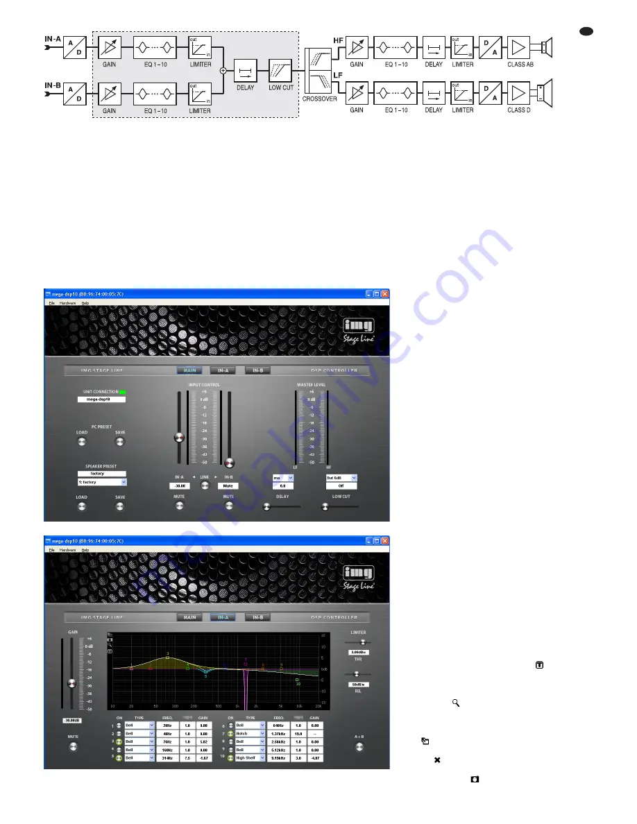
amplifier (GAIN), the 10-band sound adjustment
(EQ) and the level limiter (LIMITER) before they
are mixed. For the resulting mixed signal, a
delay (DELAY) and a high pass filter (LOW CUT)
can be set. The user can configure the signal
path described up to this point and highlighted by
a frame in the block diagram. The following sig-
nal-processing steps are factory-defined: fre-
quency split to the two output branches HF and
LF and for each of them sound correction, signal
delay, level limiting, D  /A conversion. The LF sig-
nal is transmitted to the amplifier (class D) of the
bass speaker; the HF signal is transmitted to the
amplifier (class AB) of the tweeter.

6.4.1

Setting the gain

The gain can be separately set for both input sig-
nals. To do so, use the slider INPUT CONTROL
in the main window (fig. 5) or the slider GAIN in
the configuration window of the respective input
IN-A (fig. 6) or IN-B. Alternatively, instead of set-
ting the value by means of the sliders, enter the
numeric value (in dB) beneath the sliders.  

Next to each of the sliders, a scale indicating

the selected input level is provided. The resulting
levels of the tweeter (HF) and the bass speaker
(LF) are indicated on the right-hand side of the
main window.

17

GB

Block diagram

6.4.2

Muting the input

To mute an input, click the button MUTE beneath
the corresponding gain slider in the main window
or in the configuration window of the respective
input IN-A or IN-B. While the input is muted, the
button MUTE has a red contour. To switch on the
sound, click the button MUTE again.

6.4.3

Sound correction

In the lower section of the configuration window
for IN-A and IN-B, 10 parametric equalizers (fil-
ters) are provided. Combine these filters to per-
form highly complex sound corrections (e. g. to
adapt the system to the room acoustics). 

1) Click the button ON at the beginning of a filter

row to switch a filter on (button has a green
contour) or off. 

2) In the field TYPE, select the filter characteris-

tic: Bell, Notch, AllPass, Low Shelf, High
Shelf, Band Pass, High Pass or Low Pass.

3) In the field FREQ., enter the filter frequency

desired. 

4) In the field Q, enter the quality factor desired

or, as an alternative, the relative bandwidth
BW. Click [Q] or [BW] to switch between
these two parameters. 

5) In the field GAIN, enter the amplification fac-

tor desired. The availability of this parameter
depends on the filter characteristic selected. 

6.4.3.1 Frequency response

The effects of the filter settings on the amplitude
frequency response are represented by means
of curves. Each filter is assigned a reference
point (small square with number) and a coloured
frequency curve. A white curve shows the fre-
quency response resulting from all active filters. 

Some of the filter parameters can also be set
graphically. To do so, move the appropriate ref-
erence point, using the mouse.

– To change the frequency, move the mouse

horizontally

– To change the gain, move the mouse verti-

cally

–- To change the quality factor/bandwidth,

press the right mouse button and move the
mouse horizontally

– To switch a filter on or off, double-click the

reference point

While being changed, the values are shown at
the reference point. To show them permanently
at the reference point, click the icon 

on the

edge of the graphic. To hide the values, click the
icon again. 

For fine adjustment by means of the mouse,

click the icon

on the edge of the graphic. To

return to the rough adjustment, click the icon
again. 

For a larger display of the curve, click the

icon

. For a full-screen display, click the icon

again. To return to a small curve display, click
the icon

To save the graphic as an image (png for-

mat), click the icon

.

Window for the settings of an input

Main window for configuring a speaker

Summary of Contents for MEGA-DSP 08

Page 1: ...estellnummer 25 4760 MEGA DSP12 Bestellnummer 25 4770 MEGA DSP15 Bestellnummer 25 4780 AKTIV LAUTSPRECHERBOX MIT FERNSTEUERBAREM SIGNALPROZESSOR ACTIVE SPEAKER SYSTEM WITH REMOTE CONTROLLABLE SIGNAL PROCESSOR BEDIENUNGSANLEITUNG INSTRUCTION MANUAL ...

Page 2: ...C Software 5 6 2 Einrichten der Netzwerkverbindung 5 6 3 Steuerprogramm 5 6 3 1 Gerätegruppen 6 6 3 1 1 Neue Gruppe bilden 6 6 3 1 2 Gruppe löschen 6 6 3 2 Programmpasswort ändern 6 6 3 3 Demo Modus 6 6 3 4 Firmware Update 6 6 3 5 BGM Player 6 6 3 6 Programm beenden 6 6 4 Lautsprecher konfigurieren 6 6 4 1 Verstärkung einstellen 7 6 4 2 Eingang stummschalten 7 6 4 3 Klangkorrektur 7 6 4 3 1 Freque...

Page 3: ...chäden übernom men werden 3 Einsatzmöglichkeiten Die Lautsprecherboxen der MEGA DSP Serie sind leistungsfähige Aktiv Lautsprecherboxen in robusten Holzgehäusen Sie sind vielseitig ein setzbar z B für Tanzveranstaltungen zur Aus stattung kleinerer Bühnen oder als Monitorlaut sprecher in einer Band Die Lautsprecher sind als 2 Wege Systeme ausgeführt mit jeweils einem eigenen Verstärker für den Hocht...

Page 4: ... mehr möglich 5 1 Betrieb ohne Computer Für den Einzelbetrieb darf die Lautsprecherbox nicht über ein Netzwerk mit einem Computer verbunden sein auf dem das Steuerprogramm läuft 1 Mit dem Regler MASTER VOLUME 5 die Lautstärke für den Eingang LINE A MIC 10 einstellen 2 Mit dem Regler SELECT ENTER 6 die Lautstärke für den Eingang LINE B 11 und AUX 12 einstellen Der eingestellte Verstärkungswert in d...

Page 5: ...Netz werk voreingestellt Existiert in dem angeschlos senen Netzwerk kein DHCP Server wird die Lautsprecherbox automatisch selbst zum DHCP Server und teilt den anderen Teilnehmern des Netzwerkes jeweils eine IP Adresse zu wenn diese Teilnehmer auf den automatischen Bezug von Netzwerkeinstellungen eingestellt sind Sollen im Netzwerk nur feste IP Adressen verwendet werden kann der Lautsprecherbox auc...

Page 6: ...halten Sie die Signalquellen aus oder reduzieren Sie deren Ausgangspegel damit es nach dem Zurücksetzen der Einstellungen nicht zu unerwartet hoher Lautstärke kommt Um die Firmware einer Lautsprecherbox auf den neuesten Stand zu bringen den Menüpunkt Tools Enable Update aufrufen Am rechten Rand der Liste wird jetzt zusätzlich die Spalte Update angezeigt 1 In der Zeile der entsprechenden Lautspre c...

Page 7: ...b 6 und IN B Alternativ zum Verschieben eines Reglers mit hilfe der Maus lässt sich der Wert auch nume risch in dB in das Feld darunter eingeben Parallel neben den Reglern befindet sich jeweils eine Balkenanzeige für den Eingangs pegel Die Anzeigen der resultierenden Pegel für den Hochtonlautsprecher HF und den Bass lautsprecher LF befinden sich auf der rechten Seite des Hauptfensters 6 4 2 Eingan...

Page 8: ...uf den Knopf LINK unter halb der Verstärkungsregler klicken oder in den Konfigurationsfenstern für die Eingänge auf den Knopf A B rechts unten 2 Es erscheint ein Hinweis dass mit diesem Schritt alle bisherigen Einstellungen des Ein gangs IN A vom Eingang IN B übernommen werden Die Meldung mit OK bestätigen oder den Vorgang mit Cancel abbrechen 3 Während der Kopplung der Eingänge sind die Knöpfe LI...

Page 9: ...ie Lautsprecherbox zugegriffen werden Die verbleibenden Einstellmöglichkeiten an der Lautsprecherbox hängen von der aktuellen Einstellung der Zugriffsrechte Kap 6 6 6 ab Das neue Passwort wird in der Lautsprecherbox gespeichert 6 6 3 Netzwerkeinstellungen ändern Um die Netzwerkeinstellungen für die Lautspre cherbox zu ändern 1 Den Menüpunkt Hardware Configure Network Settings aufrufen Das Dialog f...

Page 10: ...schaltet oder vom Netz getrennt wird muss das Passwort bei einem erneuten Aufruf dieser Lautsprecherbox über die Schaltfläche in der Liste Abb 2 3 nicht noch einmal eingegeben werden Soll dennoch eine erneute Eingabe des Passwortes erzwungen werden den Menüpunkt Hardware Lock Unit aufrufen Es erscheint ein Hinweis dass anschließend nur ein Zugriff auf die Einstellungen der Lautsprecherbox über das...

Page 11: ...11 ...

Page 12: ...15 6 2 Establishing a network connection 15 6 3 Control program 15 6 3 1 Unit groups 16 6 3 1 1 Creating a new group 16 6 3 1 2 Deleting a group 16 6 3 2 Changing the program password 16 6 3 3 Demo mode 16 6 3 4 Firmware update 16 6 3 5 BGM player 16 6 3 6 Exiting the program 16 6 4 Configuring the speaker 16 6 4 1 Setting the gain 17 6 4 2 Muting the input 17 6 4 3 Sound correction 17 6 4 3 1 Fre...

Page 13: ...ems in rugged wooden housings They are suitable for a wide range of applications e g for dances for smaller stages or as monitor speakers for bands The speakers are designed as 2 way systems Each of them is provided with a separate ampli fier for the bass speaker and tweeter ranges The amplifiers are equipped with protective cir cuits against overload and overheating The speaker systems include tw...

Page 14: ...0 2 Use the control SELECT ENTER 6 to adjust the volume for the inputs LINE B 11 and AUX 12 The gain value adjusted in dB is shown on the display 4 e g In A Gain 20 00dB If both input channels are linked due to a preset the upper line will show the following In AB Gain In this case each of the two controls will always adjust the volume of both channels Functions of the status LEDs 1 The LEDs SIGNA...

Page 15: ...HCP server in the network connected the speaker system will automatically assume the role of a DHCP server and will allocate an IP address to each of the other network members that are defined to automatically obtain network settings If only specific IP addresses are to be used a particular IP address can be manually as signed to the speaker system chapter 6 6 3 When in standalone operation the mo...

Page 16: ...e updated click the button in the column Update 2 A message appears which informs the user that it is not allowed to switch off the speaker system or to interrupt the connection during the multi step update process If the update fails it must be started again Click the button OK to start the update or click Cancel to cancel the update 3 Upon completion of the update another mes sage appears Confir...

Page 17: ...dapt the system to the room acoustics 1 Click the button ON at the beginning of a filter row to switch a filter on button has a green contour or off 2 In the field TYPE select the filter characteris tic Bell Notch AllPass Low Shelf High Shelf Band Pass High Pass or Low Pass 3 In the field FREQ enter the filter frequency desired 4 In the field Q enter the quality factor desired or as an alternative...

Page 18: ...le They may be loaded and used as a basis for user defined configurations Note The five pre defined factory presets cannot be changed The settings of these factory presets apply to the factory configured part of the signal processing chain and are not visible in the configuration menus 6 5 1 Loading a preset To load a preset from the storage of the speaker system 1 In the main window MAIN from the...

Page 19: ...utomatically or provided that no DHCP server exists if the speaker system is to configure the other network members To be configured by the speaker system the other members must be defined to automatically obtain the IP address 3 If a specific IP address is to be used select the option Configure Network Manually Enter the IP address in the field IP Address and the subnet mask of the net work to be...

Page 20: ...he list figs 2 3 To enforce a re entry of the password call up the menu item Hardware Lock Unit A message is shown informing you that the correct password will then be required to access the set tings of the speaker system Locking options System information 20 GB All rights reserved by MONACOR INTERNATIONAL GmbH Co KG No part of this instruction manual may be reproduced in any form or by any means...

Page 21: ... MONACOR INTERNATIONAL GmbH Co KG Zum Falsch 36 28307 Bremen Germany Copyright by MONACOR INTERNATIONAL All rights reserved A 1440 99 02 06 2014 ...

Reviews: