4
Aufstellmöglichkeiten
Die Frequenzweiche ist speziell für die Montage in
ein Rack (482 mm/19") ausgelegt. Sie kann bei Be-
darf aber auch frei aufgestellt werden. Für den Rack-
einbau wird 1 Höheneinheit (= 44,5 mm) benötigt.
5
Betriebsmodus einstellen
1) Mit der Taste (21) die Grenzfrequenz für den Sub-
woofer einstellen (siehe technische Daten des
Subwoofers):
Taste nicht gedrückt:
80 Hz
Taste gedrückt:
120 Hz
2) Mit den Tasten (23 + 25) den Betriebsmodus ein-
stellen:
Tasten nicht gedrückt: 3-Wege-Betrieb
Tasten gedrückt:
2-Wege-Betrieb
Bei 2-Wege-Betrieb sind nur die Kanäle LOW und
HIGH aktiv. Zur Kennzeichnung sind die gelben
LEDs (4) über den Reglern MID aus.
3) Bei 2-Wege-Betrieb ist die Trennfrequenz für die
Kanäle LOW und HIGH ab Werk so eingestellt,
daß sie zwischen 70 Hz und 1 kHz mit den Reg-
lern (9) gewählt werden kann. Es leuchten nur die
gelben LEDs (2) über den Reglern (9).
Bei Bedarf kann die Trennfrequenz so einge-
stellt werden, daß sie zwischen 910 Hz und 8 kHz
mit den Reglern (10) gewählt werden kann. Die-
ses darf nur von einer autorisierten Fachkraft
durchgeführt werden. Dazu das Gerät zuerst von
der Stromversorgung trennen und dann öffnen.
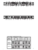
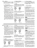
Im Gerät sind die Brücken J 1 - J 6 auf MODE 2
nach Abbildung 3 bzw. dem Aufdruck auf dem
Gerät umzustecken. Nach dem Umstecken leuch-
ten bei 2-Wege-Betrieb nur die gelben LEDs (2)
über den Reglern (10).
6
Gerät anschließen
Vor dem Anschluß bzw. vor dem Verändern von An-
schlüssen die Frequenzweiche und alle anderen
Audiogeräte ausschalten.
6.1 Eingänge
An die Eingangsbuchsen (26 + 27) die Signalquelle
(z. B. Mischpult, Vorverstärker) anschließen. Die Ein-
gänge sind symmetrisch, können aber auch asym-
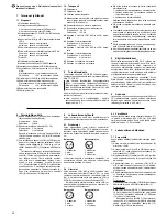
metrisch beschaltet werden. Die Stecker für die Ein-
gangsbuchsen müssen wie abgebildet angeschlos-
sen sein:
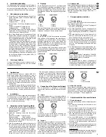
symmetrisch
asymmetrisch
1 Masse
1 Masse
2 Plus
2 Signal
3 Minus
3 Masse
Damit die Stereokanäle nicht vertauscht werden, ist
zu empfehlen, immer Kanal 1 für den linken Kanal zu
verwenden und Kanal 2 für den rechten Kanal.
6.2 Ausgänge
An die Buchsen (22) die Endverstärker der Kanäle
LOW, MID und HIGH (jeweils für den rechten Kanal)
anschließen und an die Buchsen (24) die entspre-
chenden Endverstärker für den linken Kanal. Bei
2-Wege-Betrieb sind nur die Ausgänge LOW und
HIGH zu verwenden. Den Verstärker für den Sub-
woofer an die Buchse (20) anschließen.
Alle Ausgänge sind symmetrisch, können aber
auch asymmetrisch beschaltet werden. Die Stecker
für die Ausgangsbuchsen müssen wie abgebildet an-
geschlossen sein.
symmetrisch
asymmetrisch
1 Masse
1 Masse
2 Plus
2 Signal
3 Minus
3 frei
6.3 Netzanschluß
Zuletzt das beiliegende Netzkabel mit dem Anschluß
(17) verbinden, und den Netzstecker des Kabels in
eine Steckdose (230V~ / 50 Hz) stecken. Die Fre-
quenzweiche aber noch nicht einschalten. Zuerst
muß eine Grundeinstellung erfolgen, siehe Kap. 7.1
„Grundeinstellung“.
7
Frequenzweiche einstellen
7.1 Grundeinstellung
Vor dem ersten Einschalten muß eine Grundeinstel-
lung vorgenommen werden:
1) Die beiden Pegelregler (8) für die Eingänge auf
Minimum (-10 dB) stellen.
2) Die sechs Pegelregler (12) der Ausgänge LOW,
MID und HIGH sowie den Regelregler (14) für den
Subwoofer-Ausgang auf Minimum (-20 dB) stel-
len.
3) Die sechs Mute-Tasten (3) für die Kanäle LOW,
MID und HIGH sowie die Mute-Taste (5) für den
Subwoofer-Kanal dürfen nicht gedrückt sein.
4) Die sechs Tasten PHASE (11) für die Kanäle
LOW, MID und HIGH sowie die Taste PHASE (13)
für den Subwoofer-Kanal dürfen nicht gedrückt
sein, d. h. die Phasenlage der Kanäle wird nicht
verändert.
5) Die Trennfrequenzen sind entsprechend der ver-
wendeten Lautsprecher (siehe technische Daten
der Lautsprecher) und für beide Kanäle gleich ein-
zustellen:
3-Wege-Betrieb
Bei 3-Wege-Betrieb die Trennfrequenz LOW/MID
mit den Reglern (9) und die Trennfrequenz MID /
HIGH mit den Reglern (10) einstellen.
2-Wege-Betrieb
Bei 2-Wege-Betrieb im Modus 1 [Werkseinstel-
lung, LEDs (2) über den Reglern (10) sind aus] die
Trennfrequenz LOW/HIGH mit den Reglern (9)
einstellen. Die Regler (10) sind außer Betrieb.
2
1
3
2
1
3
1
2
3
1
2
3
3
Applications
With the electronic crossover network MCX-3210
stereo audio systems can be realized in 3-way or
2-way operation with or without additional subwoofer.
The network has especially been designed for the
professional use on stage, in the disco, and for PA
applications. Due to the versatile facilities of adjust-
ment the most different requirements can be met in
an optimum way.
The frequency range limiting is made with “Active
State Variable Filters” which provide perfect transi-
tion crossovers. All inputs and outputs are balanced
(XLR jacks) but they can also be used unbalanced.
4
Installation
The crossover network has especially been designed
for the mounting in a rack (482 mm/19"). If required,
it can also be used as a free standing crossover net-
work. For the rack installation a height of 1 rack
space (= 44,5 mm) is necessary.
5
Adjustment of the Operating Mode
1) With the button (21) adjust the cut-off frequency
for the subwoofer (see subwoofer specifications):
Button not pressed:
80 Hz
Button pressed:
120 Hz
2) Adjust the operating mode with the buttons
(23 + 25):
Buttons not pressed: 3-way operation
Buttons pressed:
2-way operation
With 2-way operation only the channels LOW and
HIGH are active, the yellow LEDs (4) above the
MID controls do not light.
3) With 2-way operation the crossover frequency for
the channels LOW and HIGH is set in the factory
in such a way that it can be selected between
70 Hz and 1 kHz with the controls (9). Just the yel-
low LEDs (2) above the controls (9) are lighting.
If required, the crossover frequency can be ad-
justed in such a way that it can be selected be-
tween 910 Hz and 8 kHz with the controls (10).
This must only be carried out by authorized, skilled
personnel. For this cut off the crossover network
from the power supply and then open it. Inside the
jumpers J 1-J 6 on mode 2 are to be rearranged
according to fig. 3 resp. according to the imprint
on the crossover network. With 2-way operation
just the yellow LEDs (2) above the controls (10)
light after rearranging.
6
Connection of the Crossover Network
Prior to connection or changing of connections
switch off the crossover network and all other audio
units.
6.1 Inputs
Connect the signal source (e. g. mixer, preamplifier) to
the input jacks (26 + 27). The inputs are balanced, but
they can also be used in an unbalanced way. The
plugs for the input jacks must be connected as follows:
balanced
unbalanced
1 ground
1 ground
2 plus
2 signal
3 minus
3 ground
In order not to mix up the stereo channels, it is
recommended always to use channel 1 for the left
channel and channel 2 for the right.
6.2 Outputs
Connect the power amplifiers of the channels LOW,
MID, and HIGH (each for the right channel) to the
jacks (22) and the corresponding power amplifiers for
the left channel to the jacks (24). With 2-way opera-
tion only use the outputs LOW and HIGH. Connect
the amplifier for the subwoofer to the jack (20).
All outputs are balanced but they can also be
used in an unbalanced way. The plugs for the output
jacks must be connected as follows:
balanced
unbalanced
1 ground
1 ground
2 plus
2 signal
3 minus
3 not connected
6.3 Mains Connection
Finally connect the enclosed mains cable to the con-
nection (17), and put the mains plug of the cable into
a socket (230V~ / 50 Hz). But do not yet switch on the
crossover network. At first a basic adjustment must
be made, see chapter 7.1 “Basic adjustment”.
7
Adjustment of the Crossover Network
7.1 Basic adjustment
Prior to the first switching on a basic adjustment must
be made:
1) Set both level controls (8) for the inputs to mini-
mum (-10 dB).
2) Set the six level controls (12) of the outputs LOW,
MID, and HIGH as well as the level control (14) for
the subwoofer output to minimum (-20 dB).
3) The six mute buttons (3) for the channels LOW,
MID, and HIGH as well as the mute button (5) for
the subwoofer channel must not be pressed.
4) The six PHASE buttons (11) for the channels
LOW, MID, and HIGH as well as the PHASE but-
ton (13) for the subwoofer channel must not be
pressed, i. e. the phase condition of the channels
is not changed.
5) Adjust the crossover frequencies according to the
speakers used (see specifications of the speakers),
they must be the same for both channels.
3-way operation
With 3-way operation adjust the crossover frequency
LOW/MID with the controls (9) and the crossover
frequency MID/HIGH with the controls (10).
2
1
3
2
1
3
1
2
3
1
2
3
5
GB
D
A
CH


