DAC6800
+
BCA4 and DAC6800
+
BCA4Z Installation and Operation Manual
19
Chapter 2: Installation
2. Remove the module from the 6800
+
frame.
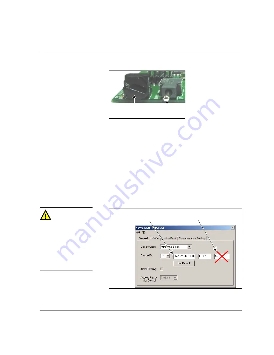
Figure 2-13.
Buttons on a Typical Card Edge
3. Set the hex switch to F.
4. While pressing the Navigation toggle switch down, reinsert the
module into the frame and then release the Navigation toggle
switch.
5. If the affected module has not been discovered by your CCS
software application, enter Build mode, and then drag or copy and
paste the module’s device icon from the catalog folder into the
Network
or
Discovery
folder.
6. Right-click the device icon, and then select
Properties
.
7. On the
Device
tab of the
Navigation Properties
box, enter the IP
address of the frame that holds the module. (See
.)
Figure 2-14.
Navigation Properties Box
Mode select rotary
(hex) switch
Navigation toggle
switch
Caution
Do not make changes in the last
field (located above and to the
right of the
Set Default
button.)
Making changes to this field
could cause loss of
communication between the
module and your CCS software.
If communication is lost, you
will need to rediscover the
module.
Do not make changes in
this field
Enter frame IP number here
Summary of Contents for DAC6800 plus BCA4
Page 7: ...vi DAC6800 BCA4 and DAC6800 BCA4Z Installation and Operation Manual Contents...
Page 35: ...22 DAC6800 BCA4 and DAC6800 BCA4Z Installation and Operation Manual Chapter 2 Installation...
Page 57: ...44 DAC6800 BCA4 and DAC6800 BCA4Z Installation and Operation Manual Index...
Page 58: ......


