Setup and Assembly Manual
Page 21
A.10.3 Powering up the WideTEK 25
The main power switch is found above the power connector. Picture 7 shows the position
of the power connector and main power switch.
Connect the power cable with the electrical outlet and switch the main power switch to
position
I
. When the main power switch is in position
I
, the scanner is in stand-by mode.
NOTE:
While using the WideTEK 25 in work conditions, it should
only be switched on and off by the touch panel
!
A.11
WideTEK 25 Touch Panel
The WideTEK 25 parameters can be set and modified with the integrated touch panel. It
shows an easy-to-use menu and helps the user to control all scanner parameters with the
touch of a finger.
When the WideTEK 25 is powered up using the main power switch, the touch panel is
illuminated in a dimmed mode and s hows the stand-by screen. The stand-by screen
shows the Image Access logo and the blinking message
Touch screen to power up
.
A.11.1 Starting the WideTEK 25 from Stand-By Mode
When the WideTEK 25 is in stand-by mode, it can be started by tapping the touch panel
on any arbitrary position. The touch panel lights up and a rotating hourglass indicates that
the start sequence is running.
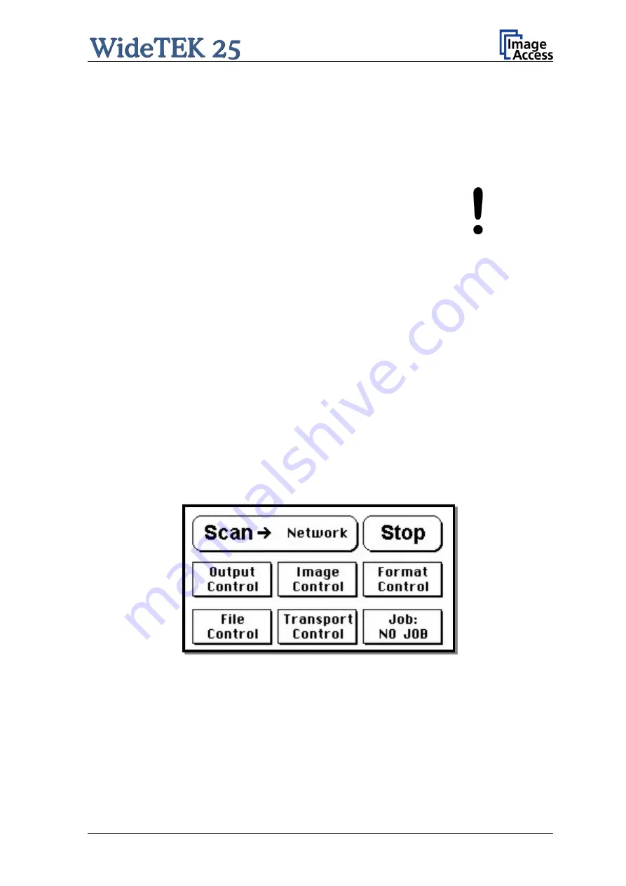
When the start-up sequence is finished, the touch panel shows the start menu screen.
Picture 8: Start menu screen


