


C A L I B R A T I O N A N D T R O U B L E S H O O T I N G
Calibration Overview
7/01
LDC-3700 Series
125
C H A P T E R
5
stabilize.
When the measured value (display) is stable and the Controller is ready to proceed, enter
the value by issuing the "TEC:V <nrf value>" command, where the actual TEC voltage on
the DMM is the <nrf value>. Once the actual TEC voltage value is entered via the
"TEC:V<nrf value>" command, the new calibration value is stored into non−volatile
memory.
Note:
To ensure measurement stability of the actual TEC voltage value when the
measurement is taken as a part of an automated test, the DMM measurement should be
polled in a loop. When the measured value is consistent within one digit for 5 seconds (for
example), the actual TEC voltage value could be considered stable.
If the "*OPC?" query is issued during TEC voltage calibration, the time out period of the
GPIB driver should be at least one minute to prevent the GPIB driver from timing out and
"hanging" the system. Refer to your GPIB driver instruction manual for information on
setting the GPIB driver time out period.
5
The controller will drive the output current to a value of about 0.12 Amps, so that the TEC
voltage will be about +6.00 volts.
6
Repeat step 4. After the value for the positive polarity of the TEC voltage is entered, the
Controller will automatically store the new calibration values for TEC voltage
measurement.
Current Source Calibration
There are three calibration adjustments required for the LASER current source of the LDC−3700B
Series Laser Diode Controller. They are calibration of the constant current source for both
bandwidths and ranges, calibration of the laser voltage measurement, and calibration of the
constant light power (I
PD
) feedback circuits.
The LDC−3700B Series Laser Diode Controller implements a two−point calibration for the Laser
current source. Two currents (approximately 20% and 80% of FS) are applied to a test load, and the
resulting actual currents are fed back (by the user) to the Controller. The Laser Controller calibration
program uses the two sets of data to calculate new calibration constants. These calibration
constants are used to set the actual current of the current source.
The following procedure is for calibrating each range of the current source. Start with the low range.
After calibration is complete in this range, switch to the high range and repeat the procedure.
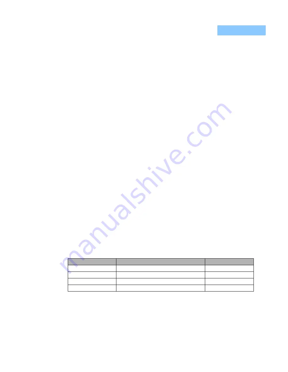
Configure the Controller in the following manner for the Laser Controller calibration:
1
Measure and record the resistance of a 1
Ω
, 20 W resistor (a 4−point probe resistance
measurement is recommended). Connect the load resistor across the LASER output
terminals (Laser Anode and Laser Cathode) on the 9 pin connector of the rear panel.
2
Connect the calibrated DMM across the load resistor. Configure the multimeter to
measure voltage in volts. You will be calculating the actual Laser current in the following
FUNCTION
STATE
GPIB COMMAND
LASER MODE
I (constant current low bandwidth)
LAS:MODE:ILBW
RANGE
low (lowest per instrument model)
LAS:RAN−x
LIMIT
90% of FS (full scale of range)
LAS:LIM:Ix
SET POINT
80% of FS (90% for LDC−3744B)
LAS:LDI
Artisan Technology Group - Quality Instrumentation ... Guaranteed | (888) 88-SOURCE | www.artisantg.com