Operating manual - English
ECODRILL 2000 CODE
23
8.4
Cutting by code
8.4.1
Choose key
Insert the suitable tracer and cutter in their respective spindles. Eliminate the tracer point spring (ch. 7.4)
and gauge.
Note: the key cutter only works with direct codes.
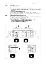
1) place the cutting pattern of the key to be cut to the left on the clamp.
2) the blank key has to be inserted into the right side.
3) from the main menu select CHOOSE KEY. Press Enter.
4) choose the manufacturer required. Press Enter.
5) choose the key model. Press Enter.
6) The display will show the cutting axes for the chosen system, e.g:
Side 1 (left) Side 2 (right) Back
7) choose the row of cuts to be carried out. Press Enter.
8) insert the cutting code from left to right, the cuts start from the head towards the tip. <Wait positioning>
will be displayed, followed by the code number sequence with the cursor underneath the first cut (The
first cut is the 1st one to the left starting from the head).
9) start the cutting operation by activating switch (Q).
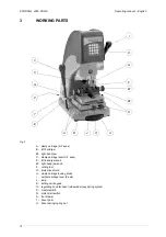
10) lower the lever (I), centre the hole on the template with the code tracer point for the first cut. The first
cutting is complete.
11) release the lever (I).
12) use the arrow button next to the “0” to change position, <Wait positioning> is displayed, then proceed.
13) once you have finished the 1st row of cuts, remove the key from the clamp and re-position it at 180°
in order to repeat the same row of cuts. After having completed this operation too, press the ESC
button.
14) <Wait positioning> will first be displayed, followed by the initial menu.
15) repeat the cutting procedure to cut other rows, if applicable.
8.4.2
PC key
Insert the suitable tracer and cutter in their respective spindles. Eliminate the tracer point spring (ch. 7.4)
and gauge.
Note: the key cutter only works with direct codes.
1) place the cutting pattern of the key to be cut to the left on the clamp.
2) the blank key has to be inserted into the right side.
3) from the main menu select: PC KEY. Press Enter
4) the manufacturer of the key required is shown. Press Enter.
5) the model is shown. Press Enter.
6) The display will show the cutting axes for the chosen system, e.g:
Side 1 (left) Side 2 (right) Back
7) choose the row of cuts to be carried out. Press Enter.
8) <Wait positioning> will be displayed, followed by the code number sequence with the cursor
underneath the first cut (The first cut is the 1st one to the left starting from the head).
9) start the cutting operation by activating switch (Q).
10) lower the lever (I), centre the hole on the template with the code tracer point for the first cut. The first
cutting is complete.
11) release the lever (I).
12) use the arrow button next to the 0 to change position, <Wait positioning> is displayed, then proceed.
13) once you have finished the 1st row of cuts, remove the key from the clamp and re-position it at 180°
in order to repeat the same row of cuts. After having completed this operation too, press the ESC
button.
14) <Wait positioning> will first be displayed, followed by the initial menu.
15) repeat the cutting procedure to cut other rows, if applicable.

