Operating manual - English
ECODRILL 2000 CODE
17
7
MACHINE REGULATION AND REGISTRATION
Before carrying out cutting operations is necessary proceed with regulation about:
•
fitting the tools and setting
•
the cross spring for Laser (sidewinder) keys.
7.1
Fitting and regulating the tools
WARNING:
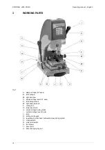
make sure that the motor start switch
(Q)
(fig.4, page 10) is turned off.
Switch on the machine with the master switch.
Select the tools for the key to be cut and proceed as follows:
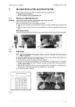
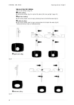
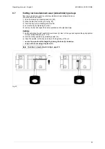
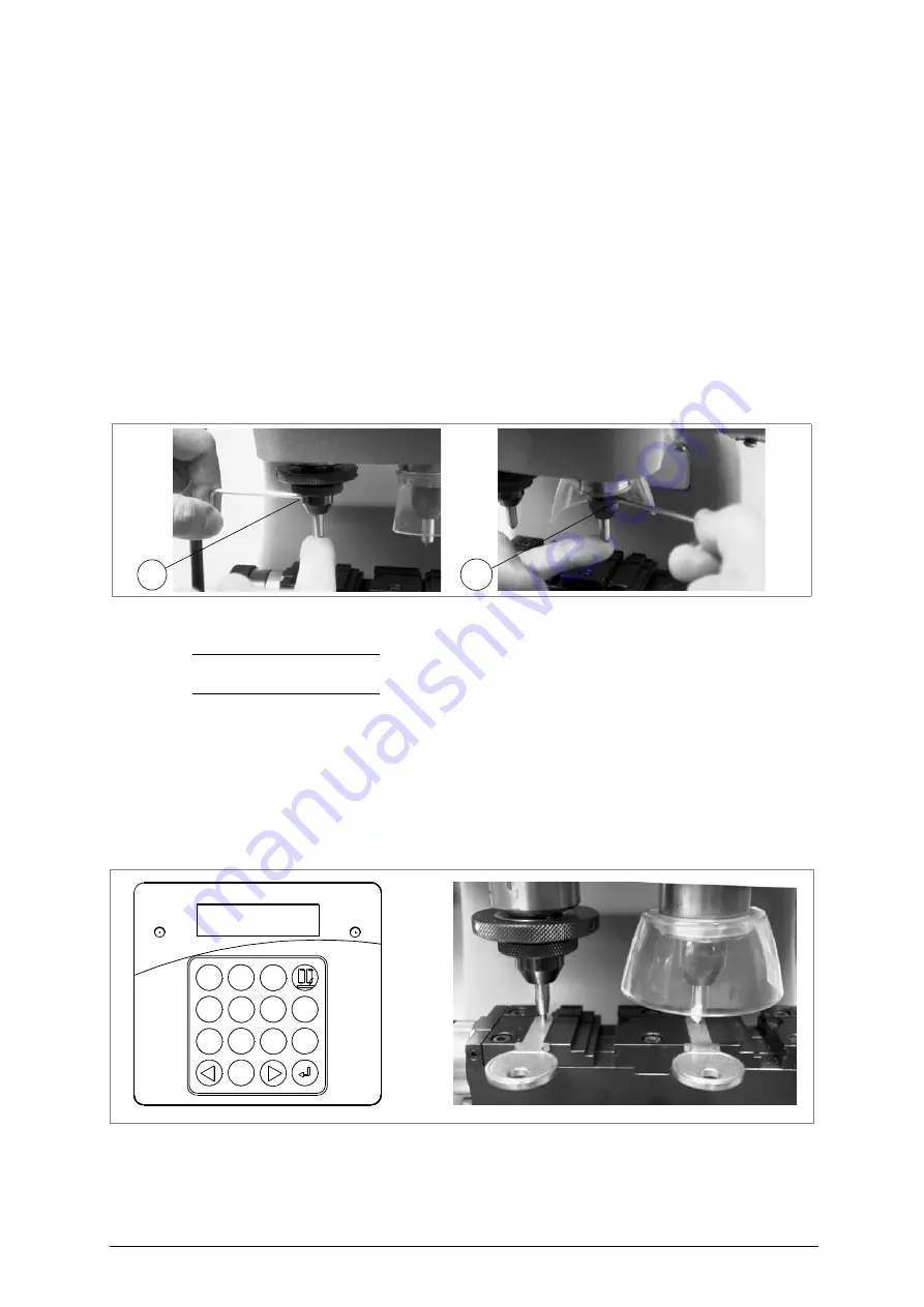
1) place the tracer point all the way into the left-hand sleeve and secure by tightening the grub screw (M)
(fig.9).
2) place the cutting tool all the way into the right-hand sleeve and secure by tightening the grub screw
(M1).
Releasing the tools
Unscrew the grub screw (M) and (M1) (fig.9) to remove the tracer point and cutting tool from the sleeves.
Fig. 9
7.2
Adjustment
Note: please note that before adjusting the machine you need to eliminate the tracer springing
(chap.7.4, page 18).
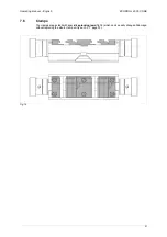
For carrying out adjustment, insert the cutter and tracer into their relative mandrils, block the bars (or 2
identical keyblanks) in the clamps and proceed as follows:
1) turn the machine on using the (P) main switch (fig.4, page 10).
2) press any key; then the top right-hand key (or choose “Adjustment” and press Enter). The message
appears <spring loaded tracer point>. Eliminate the spring and press Enter. The message appears
<put the cutter on the jaw>.
3) using the lever (I) (fig.4, page 10) lower the cutter against the bars (or keyblanks), correspondently the
two green leds will turn on and the message “Adjustment OK” will displayed.
4) the machine is ready to duplicate.
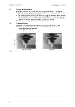
Fig. 10
M
M1
ABC
GHI
JKL
MNO
PQRS
TUV
WXYZ
DEF
1
2
3
4
5
6
7
8
9
DEL
ESC
0

