background image

3

Operation Methods

1.  Preparing for use

Using the PACK LEADER with batteries

The batteries are mounted before shipment, so the PACK LEADER can be used right away.
When replacing the batteries, use AA alkaline batteries or nickel-metal hydride batteries (ENELOOP). 

Using the PACK LEADER with 100 VAC power

Always use the enclosed AC adapter.


Always remove the batteries when using the AC adapter or when suspending the use of the 

instrument for a long time and putting the unit into storage. The instrument could be damaged 

if the battery fluid leaks.


Always use the enclosed AC adapter. Failure to do so could damage the instrument.

2.  Preparing for measurement

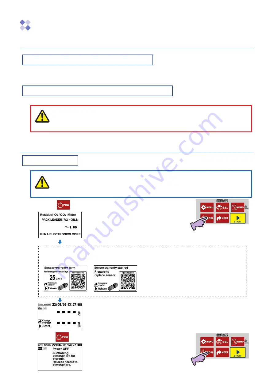
Power ON/OFF

* After turning the power OFF, wait at least two seconds before turning it ON again.


The calibration or measured value could be affected if the ambient temperature changes. In 

this case, turn the power OFF with the oxygen sensor set, and wait at least 30 minutes for 

the temperature to stabilize.


Always remove the tip of the needle from the sample before turning the power OFF.

1. 

Press 

.

The power turns ON, and the software version displays. 

(Approx. 4 seconds) 

 * The displayed details will vary according to the version.


The Measurement Standby screen opens.

* The screen on the left shows the Auto mode and Concentration 

% O

2

 setting. 

2. 

Press 

 again.

The atmosphere is automatically suctioned. After the 

screen on the left opens, the power turns OFF.

Sensor warranty term notification function 

(Displayed when the self-diagnosis function determines that 

there are 30 days or less to the end of the oxygen sensor warranty term.)

Display when 25 days are remaining       Display when 0 days are remaining (end of warranty term)

* The warranty is valid for one year from the date of shipment. 

(When the sensor is replaced, one year from the date the new sensor 

package is opened.) 

*  The display on the left is a guideline. 

The self-diagnosis results are also displayed.

Caution

Note

Summary of Contents for PACK LEADER RO-105LS

Page 1: ...les cans etc and measures the residual oxygen concentration O2 gas replacement rate REP and carbon dioxide concentration CO2 This manual describes how to operate the PACK LEADER and the precautions that must be observed to ensure proper and safe use Always read this manual and fully understand the operation before starting use Keep this manual near the device for quick reference at any time ...

Page 2: ...cks Immediately turn OFF the power switch and disconnect the power plug from the outlet Contact the dealer from which you purchased the product for repairs Take care not to stab the human body with the needle A needle is used for the measurement Handle it with extreme caution There is a risk of blindness puncture wounds or cuts Do not touch the oxygen sensor with bare hands if it is leaking A high...

Page 3: ...batteries with the designated method Do not use new and old batteries or different types of batteries together Do not heat or disassemble the batteries or place them in water or fire Do not put batteries together with metal items Do not use the battery if the outer sheath is peeling Do not use in an environment including temperature humidity pressure vibration dust or acidic or corrosive gases tha...

Page 4: ...F2 Already mounted in the main unit housing AC adapter x 1 unit Model AC 105 Needle vertical slot type x 2 pcs Needle horizontal slot type x 1 pc Switch the type when measuring a sample such as an adhesive that can easily clog the needle Adhesive rubber x 20 pcs Size 20mm x 100mm x t1 Maintenance kit model MK 105 Membrane filter x 3 pcs Check valve x 1 pc Sampling tube with fitting length 50cm x 3...

Page 5: ...will deteriorate over time and become unusable at the end of its service life Please understand and agree to the following precautions before making a purchase WA SGF2 warranty term When the sensor is already mounted in the main unit the warranty is valid for one year from the date of shipment from Iijima Electronics Corporation When purchasing the single sensor unit the warranty is valid for one ...

Page 6: ...l mode 9 Memory function Confirming the measurement history 10 Erasing the measurement history Guidance display function Procedure display 11 Various Settings and Functions 12 Setting the O2 displays O2 DISP SET 12 Setting the time TIME SET 13 Time zone selection function TIMEZONE 14 Output setting OUT SET 15 Checking for clogging CLOG CHECK 16 Initialization INITIALIZE 18 Erasing the entire histo...

Page 7: ...isplay the menu or return to the previous screen SELECT key Press to switch to the measurement history Hold for 3 seconds to switch displayed language between Japanese and English MEMORY key Press to save a measured value or delete a measured value Hold for 3 seconds to lock or unlock operations POWER key Press to turn the power ON or OFF NEXT key Press to switch the measurement mode or selection ...

Page 8: ...lt into the PACK LEADER unit and cannot be removed or mounted by the customer When the CO2 sensor has reached its life please send the PACK LEADER unit set to the dealer from which you purchased Oxygen sensor WAGNIT Model WA SGF2 The front center section has a metal mesh Product name Model Serial No Probe Probe cable Housing O ring for housing Oxygen sensor CO2 sensor already mounted inside ...

Page 9: ...rn the power OFF with the oxygen sensor set and wait at least 30 minutes for the temperature to stabilize Always remove the tip of the needle from the sample before turning the power OFF 1 Press The power turns ON and the software version displays Approx 4 seconds The displayed details will vary according to the version The Measurement Standby screen opens The screen on the left shows the Auto mod...

Page 10: ...s disconnected 1 Hold down for 3 seconds or longer on the O2 CO2 MEASURE Screen Locked displays The key lock function is enabled while Locked is displayed 2 Unlock the lock function by pressing again for 3 seconds or longer The Locked display disappears Switching the measurement mode The mode is set to Auto as the default when the unit is shipped When is pressed in the Auto mode the cycle of opera...

Page 11: ...easurement operation During calibration span calibration zero calibration operation During the clogging check operation 1 With the power turned ON hold down the for 3 seconds or longer The display language will switch from Japanese to English The displayed contents are saved Hold down for 3 seconds or longer Japanese English 2 When the is held down again for 3 seconds or longer the language will r...

Page 12: ...5 O2 when the measurement concentration is 1 O2 1 Place the needle in the atmosphere 2 Press The MENU screen opens and CAL is selected flashes 3 Press The O2 CAL screen opens If even one measurement has been taken the previous measured value will display 4 Hold down for 1 second or more The calibration starts and the Stability Decision screen opens A beep sounds CAL complete appears approx 1 secon...

Page 13: ...ens The calibration process is completed The calibration value is saved even if the power is turned OFF the batteries are removed or the AC adapter is disconnected If the Sensor error message appears refer to the section Error Messages page 32 and confirm and remedy the situation The measured value calibration value may be high or low if a strong impact is applied on the instrument unit or if the ...

Page 14: ...he sample gas Do not suction the contents A measurement error will occur if powder etc gets clogged in the needle Note that the minute amount of liquid in the sample gas is blocked by the membrane filter Warning Take care not to stab the human body with the needle There is a risk of blindness puncture wounds or cuts If pressure is applied into the pack from the set needle using an air gun etc the ...

Page 15: ...d when is not lit is read O2 CO2 measurement Manual mode 1 If the Manual mode is not enabled press This step is not required if the Manual mode is enabled The selected measurement mode is saved even when the power is turned OFF Auto mode Manual mode 2 With the Measurement Standby screen displayed hold down Suction The pump operates only while is held down In the manual mode the stability decision ...

Page 16: ...Displays for approx 1 sec Returns to normal display Confirming the measurement history The saved measured values can be displayed and confirmed later Note that if CO2 OFF is selected the CO2 measurement value is not displayed 1 When the Measurement Standby screen is displayed press The HISTORY screen opens Immediately after the screen switches three measurements with the latest date and time are d...

Page 17: ...The remedy procedure will display When QR display is pressed again the screen returns to the Error Message screen Press to cancel the display Hold down for 1 second or longer Erasing the measurement history The latest measurement value records can be deleted one item at a time Use this when a measurement value has been accidentally saved Hold down for 1 seconds or longer on the HISTORY Screen Eras...

Page 18: ... O2 100 20 9 1 When the Measurement Standby screen is displayed press The MENU screen opens Immediately after opening CAL is selected flashes 2 Press The cursor moves and SET is selected flashes 3 Press The SETTING MENU screen opens Immediately after opening O2 DISP SET is selected flashes 4 Press The O2 DISP SET screen opens CONCN O2 currently set O2 display is selected flashes 5 Press The cursor...

Page 19: ... and the time as 13 30 6 Change the time with the following steps Press The cursor will move in the order of When is pressed the cursor function will activate The time is advanced by one minute Hold down the key to advance the time 10 minutes in 0 5 second increments The time is returned by one minute Hold down the key to return the time 10 minutes in 0 5 second increments The internal clock can b...

Page 20: ... twice The cursor moves and TIMEZONE is selected flashes 3 Press The TIME SET screen opens Immediately after opening is selected flashes 4 Change the time zone with the following steps Press The cursor will move in the order of When is pressed the cursor function will activate The displayed UTC is advanced by one unit The displayed UTC is returned by one unit The time zone is returned initialized ...

Page 21: ...ted flashes 2 Press The cursor moves and SET is selected flashes 3 Press The SETTING MENU screen opens Immediately after opening O2 DISP SET is selected flashes 4 Press twice The cursor moves and OUT SET is selected flashes 5 Press The OUT SET screen opens The currently set output destination is selected flashes 6 Press and select the output destination Example To connect to the printer select PRI...

Page 22: ...kPa Check for clogging in the following types of situations 1 If Negative pressure detected displays while measuring the sample 2 If the measurement takes longer than usual or if Sensor unstable displays 3 If the measured value is higher or lower than usual Negative pressure detected display Sensor unstable display 1 When the Measurement Standby screen is displayed press The MENU screen opens Imme...

Page 23: ...ssure is not eliminated even after the needle is removed and checked remove the parts in order of the membrane filter and check valve and decide whether there is any clogging Example 2 When sample cannot be suctioned because of negative pressure and not clogging 1 Remove the needle from the sample and expose the tip of the needle to the atmosphere Then press The pump operates for 5 seconds and dec...

Page 24: ... selected flashes 2 Press twice The cursor moves and FUNC is selected flashes 3 Press The FUNC MENU screen opens Immediately after opening CLOG CHECK is selected flashes 4 Press The cursor moves and INIT is selected flashes 5 Press The INITIALIZE screen opens 6 Press The INITIALIZE complete screen displays for approx 1 second completing initialization The screen returns to FUNC MENU Initialization...

Page 25: ...yed press The MENU screen opens Immediately after opening CAL is selected flashes 2 Press twice The cursor moves and FUNC is selected flashes 3 Press The FUNC MENU screen opens Immediately after opening CLOG CHECK is selected flashes 4 Press twice The cursor moves and CLR ALL HST is selected flashes 5 Press The CLR ALL HST screen opens 6 Press The CLR ALL HST complete screen displays for approx 1 ...

Page 26: ... after opening CAL is displayed flashes 2 Press twice The cursor moves and FUNC is selected flashes 3 Press The FUNC MENU screen opens Immediately after opening CLOG CHECK is selected flashes 4 Press four times The cursor moves and CO2 FUNC is selected flashes 5 Press The CO2 FUNC MENU screen opens Immediately after opening CO2 OFF is selected flashes 6 Press The CO2 OFF screen opens The currently...

Page 27: ...xample when the upper limit setting is ON and the values detected by the sensor are O2 70 0 O2 CO2 31 0 CO2 the value displayed on the screen is O2 70 0 O2 and CO2 30 CO2 1 When the Measurement Standby screen is displayed press The MENU screen opens Immediately after opening CAL is selected flashes 2 Press twice The cursor moves and FUNC is selected flashes 3 Press The FUNC MENU screen opens Immed...

Page 28: ...cted flashes Each time is pressed the cursor will move between The display on the left shows the upper limit setting set to OFF 8 Select or and press The upper limit setting complete screen opens and the setting of the CO2 disable is completed The screen returns to CO2 FUNC MENU ...

Page 29: ...played press The MENU screen opens Immediately after opening CAL is selected flashes 2 Press twice The cursor moves and FUNC is selected flashes 3 Press The FUNC MENU screen opens Immediately after opening CLOG CHECK is selected flashes 4 Press four times The cursor moves and CO2 FUNC is selected flashes 5 Press The CO2 FUNC MENU screen opens Immediately after opening CO2 OFF is selected flashes 6...

Page 30: ...rned OFF the batteries are removed or the AC adapter is disconnected If the settings have been initialized refer to page 18 the CO2 calibration value will be initialized to the factory default state However the display on the setting screen will continue to be the most recent CO2 calibration setting value If an error message appears refer to the section Error Messages page 32 pages and confirm and...

Page 31: ...e read and the devices can be controlled by connecting to a personal computer prepared by the user A serial cross cable RS 232C is required and the personal computer must have a serial terminal RS 232C If the personal computer does not have a serial terminal prepare a USB to RS 232C converter 1 Refer to page 15 and set the output setting destination to PC 2 Connect the PACK LEADER and personal com...

Page 32: ...es its service life 6 Align the protrusion on the sensor s tip into the slot on the housing red and insert Turn the sensor clockwise and align it to the mark 7 Mount the main cover and tighten the knurled screws for the main unit cover Replacing the CO2 sensor The CO2 sensor model CS 105 is built into the PACK LEADER unit and cannot be removed or mounted by the customer When the CO2 sensor has rea...

Page 33: ...e with fingers so that it does not spin 2 Remove the check valve from the sampling tube with fitting 3 Attach a new check valve onto the sampling tube with fitting Attach so that the narrower side of the check valve faces the sampling tube The gas will not be suctioned properly if installed backward 4 Attach the membrane filter and needle If the needle or membrane filter is clogged replace it with...

Page 34: ...formation When inquiring you may be asked to provide the product information which can be displayed with the following steps Thank you for your cooperation 1 When the Measurement Standby screen is displayed press The MENU screen opens and CAL is selected flashes 2 Press twice The cursor moves and FUNC is selected flashes 3 Press The FUNC MENU screen opens Immediately after opening CLOG CHECK is se...

Page 35: ...Initialize the unit or conduct CO2 calibration again with the CO2 standard gas on hand 18 23 If the symptoms do not improve even after taking the above actions the CO2 sensor may have reached its service life or may be faulty The CO2 sensor can be replaced only by Iijima Electronics Corporation Contact the dealer from which you purchased the product for replace ment and repairs 37 The displayed O2...

Page 36: ... valve mounted in the correct direction Re mount in the correct direction so that the narrow side of the check valve faces the sampling tube 27 Is the connection of the needle membrane filter check valve or sampling tube loose Securely tighten the connection for the needle membrane filter check valve or sampling tube 26 27 Is the needle membrane filter check valve or sampling tube clogged Check fo...

Page 37: ...g the above actions the main unit may be faulty Make a request for repairs 37 The O2 measure ment value flashes The zero calibration may be faulty Initialize the unit or conduct zero calibration 18 7 Is the oxygen concentration in the atmosphere 20 O2 or less or 22 O2 or more Calibrate the span 6 If the symptoms do not improve even after taking the above actions the main unit may be faulty Make a ...

Page 38: ... a room with little temperature change where it is not affected by air conditioning 6 If the symptoms are not resolved even after taking the above actions and confirming the calibration conditions the oxygen sensor membrane may be damaged Replace the oxygen sensor with a new part Contact the dealer from which you purchased the product if the warranty is still valid 26 37 If the symptoms do not imp...

Page 39: ... sensor error message will appear and measurements will not be possible Prepare a new oxygen sensor and replace 26 Cannot calibrate sensor O2 This message indicates that the calibration cannot be performed because the oxygen sensor life has been reached The oxygen sensor has reached its service life Measurements are possible for a while but the oxygen sensor output has dropped so calibration will ...

Page 40: ...ve actions and confirming the calibration conditions the oxygen sensor membrane may be damaged Replace the oxygen sensor with a new part Contact the dealer from which you purchased the product if the warranty is still valid 26 37 If the symptoms do not improve even after taking the above actions the CO2 sensor may have reached its service life or may be faulty The CO2 sensor can be replaced only b...

Page 41: ...nutes or more Was a high concentration gas sample just measured If the sensor is exposed to high concentration gas the life could be shortened When halting measurements for two minutes or longer measure the atmosphere once to lower the concentration If the symptoms are not resolved even after taking the above actions the main unit or sensor may be faulty Make a request for repairs 37 ...

Page 42: ...n Up to 300 measurements can be saved The history can be displayed on the screen External output External connection possible with an RS 232C cable printer personal computer Other functions Automatic stability decision function With display function using progress sta tus bar Self diagnosis function Error message displayed when sensor life is reached or output error occurs etc Sensor warranty term...

Page 43: ...han Iijima Electronics Corporation 1 Conducting measurements without membrane filter mounted etc 2 Failure or damage caused by dropping etc 3 When the actual product cannot be confirmed because it is lost etc 4 Deformation or damage caused by chemicals such as organic solvents 5 Failure or damage caused by fire earthquake water damage lightning or other natural disasters 6 When the abnormality can...

Page 44: ...1 1 Ishida Toyooka cho Gamagori shi Aichi 443 0011 JAPAN Telephone 81 533 67 2827 Facsimile 81 533 69 6814 https www iijima e co jp ...

Reviews: