background image

  Draco major 

40 

2011-10-11 

4.3.6 

Training System 15 

You can have a flexible access for up to 15 students if you use the 
'Training System 15' operation mode. All of the work stations of the 
students and of the teacher are connected to the Draco major matrix with 
a interconnect cable.  

The following functions are possible: 


The teacher can get the screen content of every single student and 
can take control, if necessary. 


The screen content of the teacher can be shown to one, several or all 
of the student work stations. 


The screen content of every single student can be shown to one, 
several or all of the student work stations. 


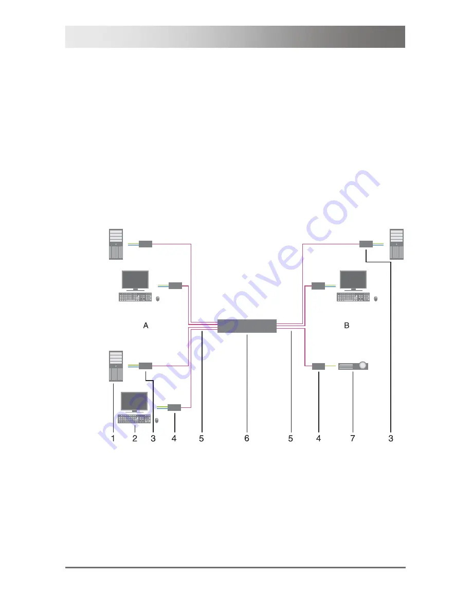
Training System 15 

A Students' 

area 

B Teacher's 

area 

Summary of Contents for Draco major K474-U8/C8

Page 1: ...IHSE GmbH Maybachstrasse 11 88094 Oberteuringen Germany info ihse de www ihse de Tel 49 7546 9248 0 Fax 49 7546 9248 48 User Manual Edition 2011 10 11 Draco major Model K474 UX CX ...

Page 2: ... the manufacturer assumes no liability for errors or omissions Neither does the manufacturer assume any liability for damages resulting from the use of the information contained herein The manufacturer reserves the right to change specifications functions or circuitry of the product without notice The manufacturer cannot accept liability for damage due to misuse of the product or due to any other ...

Page 3: ...e Views 12 3 6 1 Configuration Redundancy 12 3 6 2 Configuration Standard 1 13 3 6 3 Configuration Standard 2 14 3 7 Diagnostics and Status 15 3 7 1 Status LEDs 15 3 7 2 Status of Console Ports 17 3 7 3 Status of the CPU Ports 21 3 7 4 Network Status 24 3 7 5 Firmware Status 26 3 8 Trace Function 27 3 9 Flash Memory Status 29 4 Installation 30 4 1 Package Contents 30 4 2 System Setup 31 4 3 Exampl...

Page 4: ...rol of the Draco major 51 5 2 1 Control via OSD 51 5 2 2 Control via Java Tool 55 5 2 3 Control via LCD Display 62 5 2 4 Control via Serial Interface 66 5 3 System Settings 67 5 3 1 System 67 5 3 2 Access 71 5 3 3 Switch 74 5 3 4 Network 79 5 3 5 Date and Time 82 5 4 User Settings 84 5 4 1 User Properties 84 5 4 2 User Matrix 87 5 5 Console Settings 89 5 5 1 Console Ports CON Ports 89 5 5 2 Consol...

Page 5: ...ching 120 6 1 2 Scan Mode 121 6 1 3 Addressing of Main and Sub Matrix 122 6 1 4 Macro Keyboard 123 6 1 5 Function Keys F1 F12 123 6 2 KVM Mode 124 6 2 1 KVM List 124 6 2 2 KVM Switch Function 126 6 2 3 Follow Me Function Multicast 129 6 3 Crosspoint Mode 132 6 3 1 Crosspoint Switch Function CON Ports 132 6 3 2 Crosspoint Switch Function CPU Ports 136 6 4 Serial Interface 139 6 5 Power On and Power...

Page 6: ...ions 157 7 8 Size 157 7 9 Shipping Weight 157 8 Troubleshooting 158 8 1 External Failure 158 8 2 Failure at the Matrix 158 8 3 Blank Screen 159 8 4 Video Interference 160 9 Technical Support 161 9 1 Support Checklist 161 9 2 Shipping Checklist 161 10 Regulatory and Standards Compliance 162 10 1 CE Declaration of Conformity 162 10 2 North American Regulatory Compliance 163 10 3 WEEE 163 10 4 RoHS 1...

Page 7: ...lowed to avoid any potential damage to hardware or property loss of data or personal injury This symbol indicates important information to help you make the best use of this product Ende der Liste für Textmarke Inhalt 1 1 Spellings You can find the following spellings in the manual Spelling Description key Description of a key on the keyboard key key Press keys simultaneously key key Press keys su...

Page 8: ...approved replacements Do not use a power supply if it appears to be defective or has a damaged chassis Connect all power supplies to grounded outlets In each case ensure that the ground connection is maintained from the outlet socket through to the power supply s AC power input Do not connect the link interface to any other equipment particularly network or telecommunications equipment Only connec...

Page 9: ...raco major matrix is only specified for the use with extenders that are able to transmit video KVM and USB 2 0 signals The connection between the matrix and the KVM extenders can only be made by Cat X or fiber cables The matrix serves as a repeater Thus the matrix can be run in a maximum distance of 10 km away from the consoles and 10 km away from the sources 3 2 Access Possibilities You have the ...

Page 10: ...irectly to the source computer CPU by the provided cables Monitor s keyboard and mouse are connected to the CON units The communication between the Draco major matrix and the CPU and CON units takes place over the respective interconnect cables 1 2 3 5 3 6 4 System Overview exemplary 1 Source computer CPU 2 CPU Units 3 Interconnect cable 4 Draco major matrix 5 CON Units 6 Console monitor keyboard ...

Page 11: ...X Draco major matrix empty consisting of a basic chassis a basic circuit board a control board and a plug in power supply unit for free configuration 3 5 Accessories Part No Description 474 PSU Plug in power supply unit as a replacement or for an upgrade to a redundant power supply 474 OSD Draco major OSD card 474 DIS Draco major display card 474 C8 Draco major Cat X I O card 474 M8 Draco major fi...

Page 12: ...module CPU fiber 3 I O module console Cat X 4 I O module console fiber 5 Connect to network RJ45 6 Connect to serial interface D sub 9 pole 7 Connect to power supply unit 2 redundancy 8 Connect to power supply 1 standard 1 2 3 Front View 1 LCD display 2 Plug in power supply unit 1 standard 3 Plug in power supply unit 2 redundancy ...

Page 13: ...3 5 6 7 4 Rear View 1 I O module CPU Cat X 2 I O module CPU fiber 3 I O module console Cat X 4 I O module console fiber 5 Connect to network RJ45 6 Connect to serial interface D sub 9 pole 7 Connect to power supply 1 2 Front View 1 LCD display 2 Plug in power supply unit ...

Page 14: ...7 8 4 5 Rear View 1 I O module CPU Cat X 2 I O module CPU fiber 3 I O module console Cat X 4 I O module console fiber 5 LCD display 6 Connect to network RJ45 7 Connect to serial interface D sub 9 pole 8 Connect to power supply 1 Front View 1 Plug in power supply unit ...

Page 15: ...ion on every I O module I O card Cat X 2 1 Rear View 1 Status LED left port 2 Status LED right port Pos LED Status Description Off Port offline Flashing Port online no connection via Cat X cable Link Status green On Connection via Cat X cable ok data traffic active Off Port offline 1 2 Link Status orange Flashing Port online no connection via Cat X cable ...

Page 16: ...t 2 Status LED left port 3 Status LED right port 4 Failure LED right port Pos LED Status Description Off Port offline 1 4 Failure Status red Flashing Port online SFP module failure signal Off Port offline On Port online signal ok 2 3 Link Status green Flashing Port online no signal ...

Page 17: ... Ports All of the connections between the various consoles and CPUs are shown in this menu You have the following possibilities to access the menu OSD 1 Select Status CON Ports in the main menu Menu Status CON Ports 2 Press key F1 to get to the view CPU Ports ...

Page 18: ...umber of the CPU port with keyboard and mouse connection MON Numbers of the CPU ports with video connection Java Tool Select Status CON Ports in the task area Menu View Status CON Ports In this view video only connections are displayed in orange Connections with keyboard and mouse are displayed in red Finally full KVM connections are displayed in green ...

Page 19: ..._08 n c Status Ports Draco major Menu Status Ports Video The menu consists of six pages The first four pages inform about the set video connections the last two pages inform about the set mouse and keyboard connections To open the next page press the key Page Down To open the previous page press the key Page Up The following information is shown in this menu Field Description Output Name of CPU po...

Page 20: ...CON_04 n c CON_05 n c CON_06 n c CON_07 n c CON_08 n c Status Ports Draco major Menu Status Ports mouse keyboard The following information is shown in this menu Field Description Output Name of CON port Input Name of CPU port connected to the output signal K M of the CON port ...

Page 21: ...U Ports All of the connections between the various consoles and CPUs are shown in this menu You have the following possibilities to access the menu OSD 1 Select Status CON Ports in the main menu 2 Press the key F1 to switch to CPU Ports Menu Status CPU Ports ...

Page 22: ...rt K M Number of the CON port with keyboard mouse connection MON Number of the CON port with video connection Java Tool Select Status CPU Ports in the task area Menu Status CPU Ports In this view video only connections are displayed in orange Connections with keyboard and mouse are displayed in red Finally KVM connections are displayed in green ...

Page 23: ...video connections the last two pages inform about the set mouse and keyboard connections To open the next page press the key Page Down To open the previous page press the key Page Up The following information is shown in this menu Field Description Output Name of CPU port Input Name of CON ports connected to the output signal Video of the CPU port Output Input CON_01 CPU_01 CON_02 n c CON_03 n c C...

Page 24: ...cription DHCP Display that shows if the network settings are set dynamically YES or NO IP Address Display of the IP address as entered manually or set by DHCP Subnet Mask Display of the subnet mask as entered manually or set by DHCP Gateway Display of the gateway address as entered manually or set by DHCP MAC ID Display of the MAC address of the matrix Errors Number of data packets with errors Dro...

Page 25: ...Menu Status Network LCD Display Select Status Network in the main menu DHCP YES IP adress 0 0 0 0 Subnet mask 255 255 255 0 Gateway 0 0 0 0 MAC ID 00 21 5F 01 00 AE RX TX Errors 0 0 Dropped 0 0 Station 0 6 Broadcast 0 0 Bytes 0 2064 Status Network Draco major Menu Status Network ...

Page 26: ... the following possibilities to access the menu The following information is shown in this menu Field Description Slot Assignment of single modules by a slot number Type Type of module Firmware Name of the firmware of a module including appropriate release date OSD Select Status Firmware in the main menu Menu Status Network ...

Page 27: ... 3 8 Trace Function All of the activities and switching operations of the Draco major are logged and recorded in this menu This function will be used for diagnostic purposes if there are problems with the matrix You have the following possibility to access the menu OSD Select Status Trace in the main menu ...

Page 28: ...race The following information is shown in this menu Field Description Time Time specification for the execution of an activity or a switching operation Message Accurate documentation of the execution of an activity or a switching operation ...

Page 29: ...1284 config01 sys 31284 config02 sys 31284 config03 sys 31284 config04 sys 31284 config05 sys 31284 config06 sys 31284 Status Flash Draco major Menu Status Flash Page 1 Filename Size config07 sys 31284 config08 sys 31284 modul sys 528 dmTools jar 420492 Status Flash Draco major Menu Status Flash Page 2 An asterisk at the end of a line shows a system file that cannot be changed All of the other fil...

Page 30: ...ontents Your extender package contains the following items Draco major matrix 1x power cord per built in power supply unit 1x serial control cable 1x infrared remote control 2x 19 rack mount User Manual Java tool If anything is missing contact your dealer ...

Page 31: ...to the extenders via interconnect cables Cat X or fiber Ensure that for the connection with fiber I O modules all required ports are equipped with GBICs Please assure that your interconnect cables correspond to the specifications see Chapter 7 2 Page 143 4 Connect the 5VDC power supply units to the extenders 5 If you have a dual access system please connect the monitor for the local console with t...

Page 32: ...for training or presentation purposes In addition to that you can use the Matrix in every operation mode with the function Crosspoint Switch This function can be used for example to do the total or a special switching operation s from a central place that is not possible in standard operation modes In addition to the access by OSD and with a connected keyboard the following additional access metho...

Page 33: ... for all users that means no user can be disturbed by any activity from another user 1 2 3 5 3 6 4 Single Head Matrix KVM 1 Source computer CPU 2 CPU Unit 3 Interconnect cable 4 Draco major matrix 5 CON Unit 6 Console monitor keyboard and mouse If you have a Single Head console you can also get access to Dual Head or Quad Head CPUs However control will only be given at monitor one ...

Page 34: ...y from another user 1 2 3 3 5 6 4 Quad Head Matrix KVM 1 Dual Head source computer CPU 2 CPU Unit 3 Interconnect cable 4 Draco major matrix 5 CON Unit 6 Console 2x monitor keyboard and mouse If you have a Dual Head console you can also get access to a Single Head or Quad Head CPU However the second monitor will remain black if you have a Single Head CPU and if you have a Quad Head CPU control will...

Page 35: ...from another user 1 2 3 3 5 6 4 Quad Head Matrix KVM 1 Quad Head source computer CPU 2 CPU Unit 3 Interconnect cable 4 Draco major matrix 5 CON Unit 6 Console 4x monitor keyboard and mouse If you have a Quad Head console you can also get access to a Single Head or Dual Head CPU However the second third and fourth monitor will remain dark if you have a Single Head CPU and if you have a Dual Head CP...

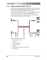
Page 36: ...SB operation mode Up to 4 USB 2 0 peripheral devices can be connected directly to the CON unit more devices can be connected by a standard USB 2 0 hub Though a non blocking access is given for all users that means no user can be disturbed by any activity from another user Single Head Matrix KVM USB 2 0 1 Source computer CPU 2 CPU Unit 3 Interconnect cable 4 Draco major matrix 5 CON Unit 6 Console ...

Page 37: ...ead KVM USB 2 0 CPU However if you have a Single Head CPU the second monitor will remain black and if you have a Quad Head CPU control will only be given at monitor one and two However control will only be given at monitor one You cannot use the USB periphery if you try to get access to CPUs without USB 2 0 connection ...

Page 38: ...ation mode Up to 4 USB 2 0 peripheral devices can be connected directly to the CON unit more devices can be connected by a normal USB 2 0 hub Though a non blocking access is given for all users that means no user can be disturbed by any activity from another user Triple Head Matrix KVM USB 2 0 1 Triple Head source computer CPU 2 CPU Unit 3 Interconnect cable 4 Draco major matrix 5 CON Unit 6 Conso...

Page 39: ...have a Triple Head KVM USB 2 0 console you can also get access to a Single Head KVM USB 2 0 CPU However the second and third monitor will remain black You cannot use the USB periphery if you try to get access to CPUs without USB 2 0 connection ...

Page 40: ...Draco major matrix with a interconnect cable The following functions are possible The teacher can get the screen content of every single student and can take control if necessary The screen content of the teacher can be shown to one several or all of the student work stations The screen content of every single student can be shown to one several or all of the student work stations Training System ...

Page 41: ... 7 Projector as an option The CPU that should be displayed on the respective monitor can be selected by the OSD or by a macro keyboard with control keys If you use the Follow Me function the screen content of the teacher can be duplicated to one or more additional monitors e g to a projector in this case the number of available students will be reduced ...

Page 42: ...ive the screen content of every single student but he cannot take over control The screen content of the teacher can be displayed on an additional monitor e g a projector The screen content of every single student can be displayed on an additional monitor e g a projector Training System 30 A Students area B Teacher s area 1 Student s work station source console 2 CPU Unit 3 Interconnect cable 4 Dr...

Page 43: ...Safety Instructions 2011 10 11 43 The CPU displayed on the teacher s monitor and on an additional monitor can be selected respectively by the OSD or by a control panel with control keys at any time ...

Page 44: ...ter CPU and up to 16 consoles Reverse Mode In reverse mode up to 16 sources computer CPU can be switched to 32 consoles The switching can be done in a number of different ways By the OSD of a console that is connected to the CON port By a PC and the Java tool By switching commands in combination with the network connection By switching commands in combination with the serial connection 1 2 3 5 3 6...

Page 45: ...Unit 3 Interconnect cable 4 Draco major matrix 5 CON Unit 6 Console e g monitor keyboard mouse and projector Any signal source can be switched to as many displays as required On these displays video can be shown at the same time In addition to that even optional audio signals can be disposed ...

Page 46: ...ces One of the Draco major matrices has to be defined as the master matrix all of the others have to be configured as slave and the IP address of the master matrix has to be entered in the field Master IP Address see Chapter 5 3 1 Page 67 They have to be connected to the master matrix by the network connector RJ45 of the CPU board The option Enable LAN Echo has to be activated at the master matrix...

Page 47: ... 2011 10 11 47 1 Dual Head source computer CPU 2 CPU Unit 3 Interconnect cable 4 Draco major matrix Master 5 Draco major matrix Slave 6 Network connection Master Slave s 7 CON Unit 8 Console 2x monitor keyboard and mouse ...

Page 48: ...led tie lines The tie lines are dynamically configured to support connections in both directions To access cascaded matrices from a console one of the matrices has to be configured as sub matrix see Chapter 5 3 1 Page 67 1 2 3 3 4 6 3 7 5 Cascading 1 Source computer CPU 2 CPU Unit 3 Interconnect cable 4 Draco major sub matrix 5 Draco major main matrix 6 CON Unit 7 Console monitor keyboard and mous...

Page 49: ... to enter and to exit Command Mode and to change the Hot Key sequence Function Keyboard Command Enter Command Mode default 2x Right Shift or Hot Key Exit Command Mode Esc Change Hot Key sequence current Hot Key c new Hot Key code Enter Until 2011 30 09 Left Ctrl Left Shift c Hot Key Code Enter Key Key Press keys simultaneously Key Key Press keys successively 2x Key Press key quickly twice in a row...

Page 50: ...Draco major 50 2011 10 11 Hot Key Code Hot Key 7 2x Right Ctrl 8 2x Right Alt In a KVM matrix configuration choose different Hot Keys for the KVM extender and the Draco U Switch ...

Page 51: ...figuration All the other submenus are described in later chapters Entering OSD 1 Open Command Mode with the Hot Key see Chapter 5 1 Page 49 2 Press o to open OSD The menu KVM List is opened as a start menu 3 Press Esc to enter the main menu If the option Listview is not active KVM Switch view will be shown Leaving OSD Press keys Shift Esc OSD will be closed without any further change and the curre...

Page 52: ...rea lowermost two text lines Keyboard control in the OSD You can navigate within the various screens with the following keys and key combinations Function Keyboard Command Left cursor only within an input field or a switching screen Cursor Left Right Cursor only within an input field or a switching screen Cursor Right In input fields Line up with wrap around In menus Line up without wrap around Cu...

Page 53: ...llow Sharing is active Switching and data transfer by save function in the menu KVM Switch screen Switching between selection fields in selection screens with two conditions e g between On Off or between Y Yes N No If Allow Sharing is active Data is additionally saved in the menu KVM Switch Space In menus with input fields Save data In menus Select menu item Enter In input fields Cancel data input...

Page 54: ...nistrator rights to set configurations Menu Login You have to login with administrator rights to be able to do configuration settings By default a user with administrator rights is predefined Login Password User admin Password admin until 2009 10 20 draco This user should be supplied with an own password as fast as possible see Chapter 5 4 1 Page 84 ...

Page 55: ...ool is available in the form of a single executable program file that does not require a separate installation Copy the tool after receiving the file to a directory on your computer If you do not have a Java tool contact your dealer Computer Connection to the Matrix For the connection between computer and matrix a crossed network cable is required Connect the network cable with the appropriate RJ4...

Page 56: ... In addition to that the user name and password according to the predefined user properties of the Draco major is requested see Chapter 5 4 1 Page 84 4 Confirm your inputs with the button OK or reject with Cancel View Connect Up to eight connections between the matrix and the Java tool can be established at the same time due to a limitation of available sockets ...

Page 57: ... The operation of the Java tool is intuitive and corresponds to the user interface of common operating systems The Java tool contains its own support function In the User Manual of the Draco major is only described how to find and open the appropriate menus in the Java tool For further operations use the Java tool support function The integrated help texts in the working area of the Java tool can ...

Page 58: ...s with more than one page Page Up Next page in input or status menus with more than one page Page Down Next field in input menus Tab Previous field in input menus Left Shift Tab Switching in selection fields between two conditions checkmark or not Öpening of already marked fields with editing or selecting possibility Space Data saving in menus Menu item selection in menus Enter Exit from tables Sw...

Page 59: ...use button twice to click on the header of the column that has to be sorted The sort is displayed by an arrow that points downwards 3 To remove the sort use the left mouse button once or twice to click on the header of the column that is sorted until the displayed arrow will disappear Filter Function The lists and tables in the Java tool are equipped with a filter function that allows a fast and s...

Page 60: ...on and select the storage location of the new configuration default or config01 08 in the menu Select Configuration 2 Select Switch Connect in the menu bar and enter the IP address of the matrix and the name and password of the user identification ein 3 Select Administration Activate Configuration in the task area and select the storage location that has been selected in point 1 4 Use the button A...

Page 61: ...dard text editor programs The following configuration parameters can be edited Parameter Description IP Default IP address of the matrix required for connection user Default user name required for connection sys dir Default directory for configuration files upd dir Default directory for update files dfw dir Default directory for the firmware status dmx dir Default directory fort he switching matri...

Page 62: ...Maybachstr 11 88094 Oberteuringen Germany Draco major 07 10 10 F02 09 Fon 49 7546 9248 0 Fax 49 7546 9248 48 www ihse de Start Menu Press the key Enter on the infrared remote control to get from the Home screen into the main menu Status Configuration Task Status Menu Draco major Menu Main Menu Navigate with the cursor keys and press the key Enter red to get to the respective submenus ...

Page 63: ...y at the Draco major can be controlled by an infrared remote control The following keys are applicable for the use with the LCD display Key Description Open OSD and select menu Open OSD and select menu Leave current menu and go back to the previous menu level Exit OSD ...

Page 64: ...ts in the input field Switch between two input fields Navigate to the beginning or the end of an input field Scroll page by page in multilateral menu items Navigate within the menu level Navigate within the input field Set parameters directly by the keypad ...

Page 65: ...Configuration 2011 10 11 65 Key Description Select between different possibilities in the selection field ...

Page 66: ...there are telegrams for an overall definition of the total switching status and for saving and loading such switching states The functionality is consistent with the switching in the Crosspoint Mode of the OSD see Chapter 6 3 Page 132 By request the Draco major optionally provides an echo of all effected switching operations via serial interface or network interface That is why you have the possib...

Page 67: ...ft corner of all menus default SWITCH_01 Info Text Additional text field for the description of the configuration default Factory settings Y Yes Configuration and remote control of the sub matrix according to the settings of the main matrix No local configuration opportunity available Note If the matrix is defined as a sub matrix the user automatically loses control in the OSD Control can be gaine...

Page 68: ...on not active default Y Yes Reject commands via external interfaces RJ45 RS232 during OSD is open Lock COM Ports N No Function not active default Baud rate kBaud Numerical value Select a predefined Baud rate for the serial control default 115 2 kBaud Y Yes Synchronize the slave matrix according to the settings of the master matrix Slave Matrix N No Function not active default Master IP Address Num...

Page 69: ...Configuration 2011 10 11 69 OSD Select Configuration System in the main menu Menu Configuration System ...

Page 70: ...o major 70 2011 10 11 Java Tool Select System System Data in the task area Menu System System Data LCD Display Select Configuration System in the main menu Menu Configuration System Sub Matrix Slave Matrix ...

Page 71: ... Yes The user can only switch to CPU ports that are unlocked for him in the User Matrix KVM switching with Hot Key commands is only possible if the user is logged in User Matrix N No Function not active default Y Yes The user can only switch from his console to CPU ports that are unlocked in the menu CON Matrix see Chapter 5 5 2 Page 93 CON Matrix N No Function not active default Y Yes If you open...

Page 72: ...matically If you select 0 seconds there will be no timeout default 0 seconds Note The timer is inactive during OSD is open Auto Logout Minutes Period of inactivity after a user is automatically logged out from the OSD at this console default 0 minutes OSD Select Configuration System in the main menu Menu Configuration System ...

Page 73: ... in the task area Menu System Access LCD Display Select Configuration Access in the main menu Enable Login N User Matrix N CON Matrix N Auto Disconnect N OSD Timeout sec 0 Auto Logout min 0 Configuration Access Draco major Cancel Save Menu Configuration Access ...

Page 74: ... as an observer to the CPU that is connected to his console Allow Sharing N No Function not active default Y Yes The User can connect to every single CPU as an operator even to such ones that are related to another user The previous user is set to observer status Note To share K M control Force Connect has to be activated Force Connect N No Function not active default Y Yes Extension of Force Conn...

Page 75: ...f there is no active connection to a CPU yet Auto Connect N No Function not active default CON Timeout Minutes Period of inactivity until the connection of the own console to the connected CPU will be automatically disconnected default 0 minutes Y Yes Activate request of keyboard control between two consoles Keyboard Connect N No Function not active default Y Yes Activate request of mouse control ...

Page 76: ...Draco major 76 2011 10 11 OSD Select Configuration System in the main menu Menu Configuration System ...

Page 77: ...sk area Menu System Switch LCD Display Select Configuration Switch 1 or Configuration Switch 2 in the main menu Allow Sharing N Force Connect N Force Disconnect N KVM Listview N KVM Auto Close N Configuration Switch 1 Draco major Cancel Save Menu Configuration Switch 1 ...

Page 78: ...Draco major 78 2011 10 11 Menu Configuration Switch 2 ...

Page 79: ...ot active default IP Address Byte Input of the IP address in the form 192 168 1 1 in combination with an operation without DHCP Subnet Mask Byte Input of the subnet mask in the form 255 255 255 0 in combination with an operation without DHCP Gateway Byte Input of the subnet mask in the form 192 168 1 1 in combination with an operation without DHCP Only modify the network parameters in consultation...

Page 80: ...Draco major 80 2011 10 11 OSD Select Configuration Network in the main menu Menu Configuration Network ...

Page 81: ...Configuration 2011 10 11 81 Java Tool Select System Network in the task area Menu System Network LCD Display Select Configuration Network in the main menu Menu Configuration Network ...

Page 82: ...n select between the following settings Field Selection Description Month 1 12 Select month Date 1 31 Select date Year 1 99 Select year Day of the week 1 7 Select day of the week Hours 0 23 Select hour Minutes 0 59 Select minute Seconds 0 59 Select second The date input should be done accordingly to the English notation with the prefixed month notation ...

Page 83: ...Configuration 2011 10 11 83 OSD Select Configuration Date Time in the main menu Menu Configuration Date Time LCD Display Select Configuration Date Time in the main menu Menu Configuration Date Time ...

Page 84: ...s User is allowed to login and access via HTTP HTTP N No Function not active Y Yes User is allowed to login and access via FTP FTP N No Function not active Y Yes User is allowed to login and access via Internet currently not realized PPP N No Function not active Y Yes User is allowed to login and access via Telnet TEL N No Function not active Y Yes User is Power User and is allowed to open crosspo...

Page 85: ...Configuration 2011 10 11 85 OSD Select Configuration User in the main menu Menu Configuration User ...

Page 86: ...ool Select User User Data in the task area Menu User User Data You can select between the following buttons Button Function Copy User Copy marked user to clipboard Paste User Paste user from clipboard Delete User Delete selected user ...

Page 87: ... the User Matrix can be activated in the system settings see Chapter 5 3 1 Page 67 If the option User Matrix is active all switching operations require a logged in user at the console Also switching by keyboard Hot Keys needs a prior login OSD Select Configuration User Matrix in the main menu Unlocked ports are marked in green all the other ports are marked in red Menu Configuration User Matrix ...

Page 88: ... without saving Save Data transfer with saving The options All and None have to be confirmed with Save or rejected with Cancel Java Tool Select User User Matrix in the task area Menu User User Matrix You can select between the following buttons Button Function Copy Matrix Copy User Matrix of the selected user to clipboard Paste Matrix Paste User Matrix from clipboard ...

Page 89: ...Head port or Triple Head USB 2 0 port Respectively only the first CON port can be still switched by Hot Keys The other ports behave like slaves If you switch to differently configured CPU ports one or more monitors can remain dark If a user switches from a Quad Head console to a Single Head CPU port the other three monitors will remain dark If a user switches from a Quad Head console to a Dual Hea...

Page 90: ...l Head port QH Quad Head port 0U USB 2 0 port 1U Single Head port with USB 2 0 port Type 3U Triple Head port with USB 2 0 port VAR OSD embedded to current resolution default OSD display screen filling 800 800x600 1024 1024x768 1280 1280x1024 1600 1600x1200 OSD 1920 1920x1200 CPU Port number Number of the CPU that is connected to this console or will be connected after saving ...

Page 91: ...R the OSD will be embedded in the current screen resolution If the monitors have different resolutions the OSD will be displayed in different sizes at the various consoles If you select a constant resolution the OSD will be displayed in full screen To this the monitor resolution will be changed This can lead to a delay regarding video display both opening and leaving the OSD ...

Page 92: ...a Menu Console CON Ports You can select between the following buttons Button Function Copy CON Copy the settings of the selected console to the clipboard Paste CON Paste the console settings from the clipboard Reset CON Reset settings of the selected console to default settings ...

Page 93: ...he following possibilities to access the menu OSD Select Configuration CON Matrix in the main menu Unlocked ports are marked in green all the other ports are marked in red Menu Configuration CON Matrix You can select between the following buttons Button Function All Selection of all CPUs None Deselection of all CPUs Cancel Abort data transfer without saving ...

Page 94: ...nfirmed with Save or rejected with Cancel Java Tool Select Console CON Matrix in the task area Menu Console CON Matrix You can select between the following buttons Button Function Copy Matrix Copy the settings of the selected console to the clipboard Paste Matrix Paste console settings from the clipboard ...

Page 95: ...ment of the vertical mouse speed default 5 Double Click 100 800 Milli seconds Adjustment of the time slot for a double click default 200 ms Keyboard Layout Region Set the OSD keyboard layout according to the used keyboard default English US Y Yes Execute OSD commands with a single click relevant with the use of touch screens to control the OSD Single Click N No Function not active default The mous...

Page 96: ...Draco major 96 2011 10 11 OSD Select Configuration System in the main menu Menu Configuration System ...

Page 97: ...d Mouse You can select between the following buttons Button Function Copy K M Copy keyboard mouse settings of the selected console to clipboard Paste K M Paste keyboard mouse settings of the selected console from clipboard Reset K M Reset mouse keyboard settings of the selected console to default settings ...

Page 98: ...supported Support of manufacturer specific protocols by request Press key F1 Menu Configuration Touch In this mask you can do the calibration of your touch screen for every single console For this purpose you are required to click at least two times at a point at the top left and at the bottom right After that you will have the opportunity to check the calibration to save it or to abort it The cal...

Page 99: ...ntrol by touch screen corresponds to the mouse control as far as possible For a smoothly control of the OSD by a touch screen the activation of the mouse keyboard setting Single Click in the OSD is recommended see Chapter 5 5 3 Page 95 ...

Page 100: ...oard should be used at the same time you will have to use an extender with four USB HID ports or an USB hub You can select between the following settings Field Selection Description Connect P1 to P2 Set bidirectional connection from console P1 to CPU P2 Connect Video P1 to P2 Set video connection from console P1 to CPU P2 Disconnect Disconnect console P1 Open P1 Open configuration file P1 Save Sav...

Page 101: ...Configuration 2011 10 11 101 OSD Select Configuration Macro Keys in the main menu Menu Configuration Macro Keys ...

Page 102: ...ected key into the clipboard Copy CON Copy macro key settings of the selected console into the clipboard Paste KEY Paste macro key settings of the selected key from the clipboard Paste CON Paste macro key settings of the selected console from the clipboard Reset KEY Reset macro key settings of the selected key to factory settings Reset CON Reset macro key settings of the selected console to factor...

Page 103: ...N port Thereby they loose their keyboard mouse control and the ability to switch If you switch to another CPU the connected consoles will follow To ensure an optimal overview the current switching status is displayed in the menu Follow Me The consoles that are selected in the menu Follow Me will only receive the possibility for control if the function is explicitly switched off from the single con...

Page 104: ...or CON Port Color CPU Port Description Green n c Available CON Port Red Red Number of CON port that is connected to the number of the CPU port or to the number of the CON port in the Follow Me mode Black Black Own CON port connection Black n c CON port not available You can select between the following functions Button Function Clear all Unlock all consoles that are connected to the own CON Port ...

Page 105: ...Configuration 2011 10 11 105 Java Tool Select Console Multicast in the task area Menu Console Multicast To make various assignments between consoles use the tab Assignment in the working area ...

Page 106: ...onfiguration information during configuration see Chapter 5 5 1 Page 89 You can select between the following settings Field Selection Description Name Text Name of the console connected to this port SH Single Head port DH Dual Head port QH Quad Head port 0U USB 2 0 port 1U Single Head port with USB 2 0 port Type 3U Triple Head port with USB 2 0 port CON Port number Number of the console that is co...

Page 107: ...Configuration 2011 10 11 107 OSD Select Configuration CPU Ports in the main menu Menu Configuration CPU Ports ...

Page 108: ...n the task area Menu CPU CPU Ports You can select between the following buttons Button Function Copy Copy the settings of the selected CPU to the clipboard Paste Paste CPU settings from the clipboard Reset Reset settings of the selected CPU to factory settings ...

Page 109: ...uration of the matrix is saved in the matrix memory As a standard the last configuration that has been saved in this way will be restored after a restart of the matrix These backup needs blocking access to the matrix memory and leads to a freeze of all OSD menus for a few seconds The switching connections are not affected by this freeze By selecting the menu item Auto Save in the system settings a...

Page 110: ...s not replace the saving of the configuration in the matrix memory see Chapter 5 7 1 Page 109 You have the following possibilities to save the configuration into files OSD Select Configuration Save as in the main menu Menu Configuration Save as Field Description Active Name and detailed information of the active configuration Note This configuration can be saved ...

Page 111: ... These memory positions can be overwritten Select the memory location that has to be overwritten with the current configuration The current configuration is saved on this memory location and is immediately displayed in the menu The previous saved configuration is deleted Java Tool Select File Save as in the menu bar Menu File Save as ...

Page 112: ...legram Reply STX 0x66 0x8C Config File No ETX ACK Assignment of a configuration file to telegram Configuration file Telegram Default sys 0x80 Config01 sys 0x81 Config02 sys 0x82 Config03 sys 0x83 Config04 sys 0x84 Config05 sys 0x85 Config06 sys 0x86 Config07 sys 0x87 Config08 sys 0x88 ...

Page 113: ...the default configuration up to eight further configurations can be loaded The selection of the configurations for a download can be made between the eight personalizable configurations and the default settings The selected configuration is loaded immediately and shown in the menu under Active The previously active configuration is deleted You have the following possibilities to load the configura...

Page 114: ...efault File 1 File 8 In the memory locations stored configurations Up to eight further configurations can be loaded besides the default configuration The selection can be made between eight personalizable configurations and the default settings Select a configuration The selected configuration is loaded immediately and is displayed as Active in the menu The previously active configuration is delet...

Page 115: ...ollowing telegram structure Telegram Reply STX 0x67 0x8C Config File No ETX ACK Assignment of a configuration file to telegram Configuration file Telegram Default sys 0x80 Config01 sys 0x81 Config02 sys 0x82 Config03 sys 0x83 Config04 sys 0x84 Config05 sys 0x85 Config06 sys 0x86 Config07 sys 0x87 Config08 sys 0x88 ...

Page 116: ...nd password means the appropriate password for the access The user must have administrator rights and ftp access rights xxx xxx xxx xxx means the current IP address of the matrix You can find the following files in the directory File Description config sys This file includes the reset configuration of the matrices internal default sys This file includes the default configuration of the matrix conf...

Page 117: ...irectory 2 Save the required configuration file on an external storage medium Note that these configuration files only work with the latest matrix firmware Compatibility to firmware updates at a later time is possible but cannot be guaranteed ...

Page 118: ...date Firmware in the task area Menu Administration Update Firmware 2 Select the directory in the lower part of the working area in which the update file can be found Open the file defaults cfg and insert in the parameter upd dir the directory from which the update files should be standardly sourced 3 Select those modules in the list that have to be updated and enable the respective checkbox in the...

Page 119: ...d period of time for one update will exceed 20 minutes cancel the update Open the file defaults cfg and set the parameter safemode to true 5 Restart the matrix after the update by pressing the button Restart matrix in the appearing popup window ...

Page 120: ...equired 6 1 Operation by Hot Keys 6 1 1 Direct Switching The direct switching by Hot Keys on a keyboard is the fastest possibility for a user to switch at his console between different CPUs There is a possibility to switch video keyboard and mouse or only video Direct Switching of Video Keyboard and Mouse 1 Start Command Mode with the Hot Key For control the LEDs Shift and Scroll flash at the keyb...

Page 121: ...he User Matrix is selected and the user is logged in the OSD 6 1 2 Scan Mode The Scan Mode offers the possibility to show video signals of the different CPUs fast and without delay and offers switching in between without continuously using the Hot Key The switching between two video signals can even take place within one frame 1 Start command mode with the Hot Key For control the LEDs Shift and Sc...

Page 122: ... Shift Left Shift m optional o OSD access in the sub matrix Left Shift Left Shift s o Example Switching to the CPU port 23 of the sub matrix Switching to the CPU Port e g 12 of the main matrix that have the connection to the sub matrix Left Shift Left Shift m 1 2 Enter Switching to the CPU Port 23 of the sub matrix Left Shift Left Shift s 2 3 Enter The selected main matrix sub matrix mode is perma...

Page 123: ...0 Up to eight commands per key can be saved in the OSD They can be retrieved sequentially by pressing a key For switching press the favored key In doing so the monitor will remain dark for a short time 6 1 5 Function Keys F1 F12 In Command Mode you can retrieve the macros 1 12 with the function keys F1 F12 of the connected standard keyboard instead of the special macro keyboard The deposited comma...

Page 124: ...VM List will be opened as a standard if you login to the OSD Alternatively the configuration can be modified in this way that the KVM Switch menu will be started see Chapter 5 3 3 Page 74 Menu KVM List All CPU ports that are unlocked for the user are shown in this menu Thereby the restrictions that are given by used CPU ports and access restrictions in the User Matrix as well as in the Console Mat...

Page 125: ...ionally Video connection to the own console Yellow Yellow CPU port bidirectionally connected to the own console Red Red CPU port bidirectionally connected to another console Red Yellow CPU port bidirectionally connected to another console Video connection with the own console The user receives a CPU port without control possibility by mouse or by touch screen only if the CPU is already used and ne...

Page 126: ... function KVM Listview in Configuration System is activated The complete and current switching status is shown in this view Menu KVM Switch The following color combinations are available Color CPU Port Color CON Port Description Green n c CPU port not connected video can be connected to another console Green Yellow CPU port not connected video can be connected to the own console ...

Page 127: ...ng is active the user will be able to switch to an already to another user assigned CPU by using the key Space and will receive the monitor display but without the opportunity to control The current user will not be informed about this procedure If Force Connect is active the user will be able to switch to any CPU by pressing the key Enter and will receive the monitor display including the opportu...

Page 128: ...Draco major 128 2011 10 11 Java Tool Select KVM Switch CON Ports in the task area Menu KVM Switch CON Ports ...

Page 129: ...ching and will also show the display content of the new CPU This function does not provide any access to the display content of other consoles The function Follow Me is helpful for example to make the display content of a presentation available for a beamer to make monitors in control rooms available for all monitoring purposes to show the own display content to an administrator if there some ques...

Page 130: ...ort Description Green n c CON Port available Red Rot CON port connected to CPU Port or with CON Port in the Follow Me mode Black Black Own CON port connection Black n c CON port available You can select between the following buttons Button Description Clear all Unlock all ports that are connected to the own console ...

Page 131: ...Configuration 2011 10 11 131 Java Tool Select Console Multicast in the task area Menu Console Multicast ...

Page 132: ...are shown For an optimal overview a matrix display is used in this case You can only assign 1x video MON and 1x keyboard and mouse control K M to any console If another CPU is selected K M or MON an existing connection will be eventually stopped You can assign 1x MON without K M to any console If you assign 1x K M to a console you will also have to assign the corresponding video signal to this con...

Page 133: ...he lines two lines with respectively 16 CPUs In the upper two lines K M of any CON port is shown to which CPU the keyboard mouse signals have to be sent In the lower two lines MON of every single CON port is shown from which CPU the video signal is displayed The switching of a single keyboard mouse or video signal is done by the key Space The combined switching of K M and MON is done by the key En...

Page 134: ...ll be closed If connections should be established or closed a popup window will open after the respective change to confirm the operation by Yes or to reject by No online check mark has to be set To connect all available CON units to a video signal from a CPU unit at the same time proceed as follows Use the right mouse button to click in the respective CPU number in the line CPU of the matrix and ...

Page 135: ...f the matrix and afterwards select the menu item Clear All CPU Channels in the opening selection list You can select between the following buttons Button Function Set Matrix Activate the switching operations done by the Java tool Reset Matrix Reset all matrix connections Reload Reload the connection overview ...

Page 136: ... overview a matrix display is used in this case You have the following possibilities to access the menu The switching function is done immediately The user has to take care of the legitimacy of the switching operation There is no control by the system OSD Select Status Crosspoint Switch in the main menu Press the key F1 to get to the menu CPU Ports Menu Crosspoint Switch CPU Ports ...

Page 137: ...e keyboard mouse control is at the moment Practically any number of monitors can be switched to a CPU in a line but always only 1x keyboard mouse K M Java Tool Select CP Switch CPU Ports in the task area Menu CP Switch CPU Ports To set a connection between a console and a source Computer CPU proceed as follows Double click with the mouse on the according matrix field and select the desired type of...

Page 138: ...of the matrix and afterwards select the menu item Set All Available Video Channels in the opening selection list To close all connections between the respective CPU and the connected consoles proceed as follows Use the right mouse button to click in the respective number in the line CPU of the matrix and afterwards select the menu item Clear All CPU Channels in the opening selection list You can s...

Page 139: ...e possibility to switch via a serial interface RS232 For the control of the Draco major via serial interface certain parameters are used Set up the following format of the serial data transfer for the communication 115 2 KBaud 8 1 NO 115 2 KBaud 8 Data bit 1 Stop bit no parity ...

Page 140: ...ect Configuration Restart in the main menu If you select the option Restart the Draco major will be restarted with the current settings 2 Select Configuration Default in the main menu If you select the option Default the Draco major will be restarted with the current settings Java Tool Select Switch Restart Matrix in the menu bar If you select the option Restart the Draco major will be restarted w...

Page 141: ... there OSD Select Configuration Reset in the main menu If you select the option Reset the Draco major will be set back into delivery status LCD Display Select Configuration Reset in the main menu If you select the option Reset the Draco major will be set back into delivery status 6 5 3 Power Down Press the On and Off button at the standard appliance outlet to power on and power off the matrix ...

Page 142: ... SFP modules can be damaged by electrostatic discharge ESD When handling care must be taken so that the devices are not damaged 7 1 3 RJ45 Network The communication of the Cat X devices requires a 1000BASE T connection The cabling has to be done according to EIA TIA 568 B 1000BASE T with RJ45 connectors at both ends All of the four wire pairs are used in both directions The cabling is suitable for...

Page 143: ...pe of Interconnect Cable The Draco major requires interconnect cabling specified for Gigabit Ethernet 1000BASE T The use of solid core AWG24 shielded Cat 5e or better is recommended Cat X Solid Core Cable AWG24 S UTP Cat 5e cable according to EIA TIA 568 B Four pairs of wires AWG24 Connection according to EIA TIA 568 B 1000BASE T Cat X Patch Cable AWG26 8 S UTP Cat 5e cable according to EIA TIA 56...

Page 144: ...ifications Single mode 9μm Two fibers 9μm I V ZN H 2E9 in house patch cable I V ZN HH 2E9 in house breakout cable I AD ZN H 4E9 in house or outdoor breakout cable resistant A DQ ZN B2Y 4G9 outdoor cable with protection against rodents Multi mode 50μm Two fibers 50μm I V ZN H 2G50 in house patch cable I AD ZN H 4G50 in house or outdoor breakout cable resistant Multi mode 62 5μm Two fibers 62 5μm I ...

Page 145: ...OM3 1 000 m 3 280 ft Multi mode 50μm 400 m 1 300 ft Multi mode 62 5μm 200 m 650 ft If you use single mode SFPs with multi mode fibers you normally can double the maximum acceptable cable length Pos 48 806 IHSE Technische Daten Verbindungskabel Verbindungskabel LWL _Steckverbinder 477 xx 5 mod_1278954447542_6 doc 43740 Type of Connector Connector LC Connector ...

Page 146: ...al Head R459 0ED Draco KVM CON Unit Dual Head L459 AES Draco KVM CPU Unit Analog Audio Single Head L459 AED Draco KVM CPU Unit Analog Audio Dual Head R459 AED Draco KVM CON Unit Analog Audio Dual Head L459 1U2 Draco KVM CPU Unit Single Head 4x USB HID R459 1U2 Draco KVM CON Unit Single Head 4x USB HID L459 2U2 Draco KVM CPU Unit Dual Head 4x USB HID R459 2U2 Draco KVM CON Unit Dual Head 4x USB HID...

Page 147: ...CPU Unit Single Head 2x USB HID 4x USB 2 0 R477 1STC Draco KVM CON Unit Single Head 2x USB HID 4x USB 2 0 L477 2S4C Draco KVM CPU Unit Dual Head 4x USB HID R477 2S4C Draco KVM CON Unit Dual Head 4x USB HID L477 SHCV Draco KVM CPU Unit Single Head DVI I Input VGA 2x USB HID KVM Extender with Cat X connection K474 Series Type Description L474 BSHC Draco KVM CPU Unit Single Head 2x USB HID R474 BSHC ...

Page 148: ... KVM CON Unit Audio Single Head L459 AMD Draco KVM CPU Unit Audio Dual Head R459 AMD Draco KVM CON Unit Audio Dual Head L459 M1U2 Draco KVM CPU Unit Single Head 4x USB HID R459 M1U2 Draco KVM CON Unit Single Head 4x USB HID L459 M2U2 Draco KVM CPU Unit Dual Head 4x USB HID R459 M2U2 Draco KVM CON Unit Dual Head 4x USB HID L459 MUT Draco KVM CPU Unit Single Head 4x USB 2 0 R459 MUT Draco KVM CON Un...

Page 149: ...ngle Head Digital Audio 4x USB HID L477 1STM Draco KVM CPU Unit Single Head 2x USB HID 4x USB 2 0 R477 1STM Draco KVM CON Unit Single Head 2x USB HID 4x USB 2 0 L477 2S4M Draco KVM CPU Unit Dual Head 4x USB HID R477 2S4M Draco KVM CON Unit Dual Head 4x USB HID L477 SHMV Draco KVM CPU Unit Single Head DVI I Input VGA 2x USB HID KVM Extender with Fiber Connection Multi Mode K474 Series Type Descript...

Page 150: ...Single Head R459 ASS Draco KVM CON Unit Audio Single Head L459 ASD Draco KVM CPU Unit Audio Dual Head R459 ASD Draco KVM CON Unit Audio Dual Head L459 S1U2 Draco KVM CPU Unit Single Head 4x USB HID R459 S1U2 Draco KVM CON Unit Single Head 4x USB HID L459 S2U2 Draco KVM CPU Unit Dual Head 4x USB HID R459 S2U2 Draco KVM CON Unit Dual Head 4x USB HID L459 SUT Draco KVM CPU Unit Single Head 4x USB 2 0...

Page 151: ...ngle Head Digital Audio 4x USB HID L477 1STS Draco KVM CPU Unit Single Head 2x USB HID 4x USB 2 0 R477 1STS Draco KVM CON Unit Single Head 2x USB HID 4x USB 2 0 L477 2S4S Draco KVM CPU Unit Dual Head 4x USB HID R477 2S4S Draco KVM CON Unit Dual Head 4x USB HID L477 SHSV Draco KVM CPU Unit Single Head DVI I Input VGA 2x USB HID KVM Extender with Fiber Connection Single Mode K474 Series Type Descrip...

Page 152: ...trices in parallel Parameter Description Command byte In the range 0x40 to 0x6F see list of allowed commands below Data bytes a Binary data In order to prevent that during the transmission of binary data control statements of control commands are transferred the data are divided into low nibble and high nibble The data are distributed to the low nibbles of two bytes and provided with an offset by ...

Page 153: ...ation Draco major Matrix Control CPU Sending of a command Acquiring of a command processing of a command blocking of further commands a Errors occurred NAK b No errors ACK ECHO c Optional Reply telegram with data a Repeat telegram b Next command c Receive and process the repeat telegram The serial interface can be blocked while OSD has been opened ...

Page 154: ...r not output STX 0x49 CPU 1 CPU 2 CPU 16 ETX ACK ECHO 4 Output off for all CON ports STX 0x4A ETX ACK ECHO CPU Receipt K M Return Channel Function Telegram Reply 5 CPU output signal from CON STX 0x4B CPU CON ETX ACK ECHO 6 CPU output off STX 0x4C CPU ETX ACK ECHO 7 CPU01 CPU32 output signal from CON 1 CON 32 Requires 32 CON 0x80 for no output STX 0x4D CON 1 CON 2 CON 32 ETX ACK ECHO 8 Output off f...

Page 155: ...l from CPU 1 CPU 16 cf telegram 3 CPU01 CPU32 output signal from CON to CON 32 cf telegram 7 STX 0x51 CPU 1 CPU 2 CPU 16 CON 1 CON 2 CON 32 ETX ACK ECHO 12 Reset switch matrix STX 0x52 ETX ACK 13 Report matrix complete setup Output of 48 values 0x80 for no output The first 16 values describe the CON port output cf telegram 3 The next 32 values describe the CPU output cf telegram 7 STX 0x53 ETX STX...

Page 156: ...y Contact 1 4 4 GND D Sub 9 Serial Picture Pin Signal Pin Signal 1 n c 6 DTR 2 CTS 7 TxD 3 RTS 8 RxD 4 DSR 9 n c 1 5 6 9 5 GND RJ45 Network Bild Pin Signal Pin Signal 1 D1 5 n c 2 D1 6 D2 3 D2 7 n c 8 1 4 n c 8 n c RJ45 Interconnect Picture Pin Signal Pin Signal 1 D1 5 D3 2 D1 6 D2 3 D2 7 D4 8 1 4 D3 8 D4 ...

Page 157: ...000 mA Fuse T2A L250V Battery Panasonic BR1225 3 V 48 mAh 7 7 Environmental Conditions Operating Temperature 41 to 113 F 5 to 45 C Storage Temperature 13 to 140 F 25 to 60 C Relative Humidity Max 80 non condensing 7 8 Size Draco major 483 x 85 x 450 mm 19 x 2U x 18 Shipping Box 500 x 500 x 100 mm 20 x 20 x 4 7 9 Shipping Weight Draco major 6 0 kg 12 9 lb Shipping Box 8 0 kg 17 2 lb ...

Page 158: ...r support 8 1 External Failure Diagnosis Possible Reason Measure Matrix cannot be started anymore Fuse at the standard appliance outlet Check fuse 8 2 Failure at the Matrix Diagnosis Possible Reason Measure Serial control impossible or only restrictedly possible Different Baud rate of CPU and matrix Adapt Baud rate in the matrix and in the CPU see Chapter 5 3 1 Page 65 Serial control via RJ45 port...

Page 159: ...ion Connection of a console with a CON port or connection of a CPU to a CPU port not established correctly Check connections regarding CON and CPU ports at the matrix LED 1 on or LED 2 off Connections CON unit matrix and CPU unit Check connecting cables and connectors No cable cable break CPU CON unit offline CPU CON unit connected to the wrong port CPU unit LED 3 green Connection between CON unit...

Page 160: ...of a 1U 2U or 3U port configuration Switch to another port No OSD card Mount OSD card Opening the OSD not possible Wrong Firmware on the OSD card Run a firmware update of the OSD card according to the extenders that are used in combination with the Draco major Incorrect video display Cable connection disturbed Check the connection length and quality of the interconnect cable to the units ...

Page 161: ...dealer if necessary Issue date of the existing manual Nature circumstances and duration of the problem Involved components such as graphic source CPU OS graphic card monitor USB HID USB 2 0 devices interconnect cable including manufacturer and model number Results from any testing you have done 9 2 Shipping Checklist 1 To return your device contact your dealer to obtain a RMA number Return Materia...

Page 162: ...pment EN 55022 2006 A1 2007 Class A EN 55024 1998 A1 2001 A2 2003 This declaration certifies the conformity to the specified directives but contains no assurance of properties The safety instructions and installation guidelines noted in this manual shall be considered in detail Compliance with the specifications for cable lengths and types is mandatory Manufacturer IHSE GmbH Maybachstrasse 11 8809...

Page 163: ...fications not expressly approved by the party responsible for compliance could void the user s authority to operate the equipment Shielded cables must be used with this equipment to maintain compliance with radio frequency energy emission regulations and ensure a suitably high level of immunity to electromagnetic disturbances All power supplies are certified to the relevant major international saf...

Page 164: ...d it is part of the PAL TV standard CON Unit Component of a Draco major or Media Extender to connect to the console monitor s keyboard and mouse optionally also with USB 2 0 devices CPU Unit Component of a Draco major or Media Extender to connect to a source computer CPU DDC The Display Data Channel DDC is a serial communication interface between monitor and source computer CPU It allows a data ex...

Page 165: ...creen Display is used to display information or to operate a device Quad Head A system with four video connections RCA Cinch A not standardized plug connection for transmission of electrical audio and video signals especially with coaxial cables SFP SFPs Small Form Factor Pluggable are pluggable interface modules for Gigabit connections SFP modules are available for Cat X and fiber interconnect ca...

Page 166: ...tandards MDA CGA and EGA 11 1 Matrix specific Glossary Term Explanation Allow Sharing Matrix function that allows switching from the own console to any CPU with video Auto Connect Matrix function that allows an automatic connection establishment between the own console and a random CPU that is available Auto Logout Matrix function that describes the duration of inactivity after the user haws been ...

Page 167: ...fter a connection establishment with a CPU in the OSD to close it and to set up the connection immediately KVM Listview Listing of all CPUs that are available fort he CPU KVM Mode The user can switch with his own console to all available CPUs in the KVM mode Macro Keys Programmable keys that can execute a stringing together of commands to the matrix Mouse Connect Matrix function that allows taking...

Reviews: