NOTE: DIAGRAMS & ILLUSTRATIONS ARE NOT TO SCALE.
15
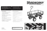
Remove Tube
Regulator
Orifice
Remove Clip
Shutter
Opening
Figure 19
In Canada:
THE CONVERSION SHALL BE CARRIED OUT
IN ACCORDANCE WITH THE REQUIREMENTS
OF THE PROVINCIAL AUTHORITIES HAVING
JURISDICTION AND IN ACCORDANCE WITH
THE REQUIREMENTS OF THE CAN/CGA-B149.1
AND .2 INSTALLATION CODE.
LA CONVERSION DEVRA ÊTRE EFFECTUÉE
CONFORMÉMENT AUX RECOMMANDATIONS
DES AUTORITÉS PROVINCIALES AYANT
JURIDICTION ET CONFORMÉMENT AUX
EXIGENCES DU CODE D'INSTALLATION CAN/
CGA-B149.1 ET .2.
Gas conversion kits are available to adapt your
appliance from the use of one type of gas to
the use of another. These kits contain all the
necessary components needed to complete the
task including labeling that must be affixed to
ensure safe operation.
Kit part numbers are listed here and the fol-
lowing steps detail the conversion procedure.
GAS CONVERSION KITS
Step 1.
Turn off the gas supply to the appliance.
Step 2.
Carefully remove the logs.
Exercise
care so as not to break the logs
.
Step 3.
Refer to
Figure 19
.
Remove the burner assembly with attached
venturi tube.
WARNING
This conversion kit shall be installed by a qualified service agency in
accordance with the manufacturer’s instructions and all applicable codes
and requirements of the authority having jurisdiction. If the information in
these instruction is not followed exactly, a fire, explosion or production of
carbon monoxide may result causing property damage, personal injury
or loss of life. The qualified service agency is responsible for the proper
installation of this kit. The installation is not proper and complete until the
operation of the converted appliance is checked as specified in the manu-
facturer’s instructions supplied with the kit. The qualified service agency
performing this installation assumes responsibility for this conversion.
AVERTISSEMENT
Cette trousse de conversion doit être installée par un technicien agréé,
selon les instructions du fabricant et selon toutes les exigences et tous les
codes pertinents de l’autorité compétente. Assurez-vous de bien suivre
les instructions dans cette notice pour réduire au minimum le risque
d’incendie, d’explosion ou la production de monoxyde de carbone pouvant
causer des dommages matériels, des blessures ou la mort. Le tecnicien
agréé est responsable de l’installation de cette trousse. L’installation n’est
pas adéquate ni complète tant que le bon fonctionnement de l’appareil
converti n’a pas été vérifié selon les instructions du fabricant fournies avec
la trousse. Le fournisseur de service qualifié ayant réalisé l'installation
assume les responsabilités liées à la conversion.
Natural to Propane Gas Conversion Kits
Model No.
Unit Type
Cat. No.
VRE4336
GCK-DB078P
H4916
VRE4342
GCK-DB078P
H4916
Propane to Natural Gas Conversion Kits
Model No.
Unit Type
Cat. No.
VRE4336
GCK-DB140N
H4915
VRE4342
GCK-DB140N
H4915
Electronic Appliances
Step 4.
Dexen Electronic Valves
- See
Figure
20
and the instructions provided with the kit.
Remove and discard the two pressure regulator
mounting screws. Remove the pressure regula-
tor and diaphragm. Discard all removed compo-
nents.
Ensure the rubber gasket installed on
the back of the replacement pressure regulator
is properly positioned.
Install the new pressure
regulator using the new screws supplied with
the kit. Tighten screws to 25 In. lb. torque.
NOTE: Natural gas regulators are identified
with a blue dot. Propane regulators have a
red dot.
Step 5.
See
Figure 21
and replace the pilot
orifice as follows: Remove pilot hood assembly
by grasping the hood and pulling the assembly
straight up. Under the hood is the pilot orifice.
With caution and using a magnetic screwdriver,
undo the pilot orifice and remove it from the
assembly. Carefully replace the orifice with the
one provided with the kit. Press the pilot hood
back over the assembly. The orientation should
be aligned as shown in
Figure 21
.
Exercise ex-
treme care to prevent damage to or breakage
of the igniter assembly.
NOTE: Propane pilot orifices are identified with
a countersink in the head. Natural gas orifices
do not have this countersink. See Figure 21.