22
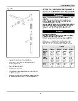
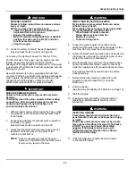
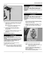
Disconnecting The Hydraulic Quick Couplers
Always make sure that the oil in the attachment has
reached operating temperature prior to disconnecting.
Disconnecting the attachment when the oil is cold may
result in damage to the system.
WARNING
BURN HAZARD
Hydraulic fluid, tubes, fittings and quick couplers can
get hot when running machine and attachments /
implements.
Be careful when connecting and disconnecting quick
couplers.
◂
W-2220
1.
Relieve hydraulic pressure. (See the machine’s
Operation & Maintenance Manual for the correct
procedure.)
2.
Push the couplers together.
3.
Retract the sleeve on the female coupler until the
couplers disconnect.
Operating The Controls
The auger is designed to be operated in both the
clockwise and counter-clockwise rotation direction.
Rotation direction is determined by the hydraulic flow
from the machine's auxiliary hydraulics.
WARNING
INSTABILITY HAZARD
Machine tipping or rollover can cause serious injury
or death.
•
Do not overload the machine.
•
Keep the lift arms as low as possible.
•
Do not travel or turn with the lift arms up.
•
Turn on level ground. Slow down when turning.
•
Go up and down slopes, not across them.
•
Keep the heavy end of the machine uphill.
•
Check for adequate traction.
◂
W-2018
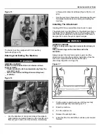
1.
Enter the machine.
2.
Turn on the machine and release the parking brake.
3.
Engage auxiliary hydraulics. (See the loader’s
Operation & Maintenance Manual for correct
procedure.)
NOTE:
The auxiliary hydraulics must be activated
prior to attachment operation.
NOTE:
See the loader’s Operation & Maintenance
Manual for more information on operation of
the Auxiliary Hydraulic System for your
model loader.
Operation With The Loader
WARNING
GENERAL HAZARD
Failure to follow instructions can cause serious
injury or death.
•
Check for underground utility lines before
digging.
•
Keep bystanders away from rotating auger and
cutting head.
•
Do not operate the auger if the point of the auger
is not touching the ground.
◂
W-2711
NOTE:
In some circumstances, based on machine
positioning and auger configuration, the
attachment may come in contact with the
machine.
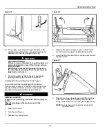
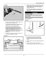
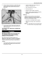
Figure 29
C221411
1.
Raise the lift arms and tilt the attachment mounting
frame forward. In this position the auger will be free
floating in the mounting frame and will allow for a
vertical hole to be drilled [Figure 29].
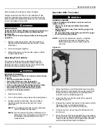
2.
Lower the lift arms until the point of the auger bit
touches the ground.
3.
Engage the auxiliary hydraulics on the loader so that
the auger turns in a clockwise direction.
(See Operating The Controls on Page 22)
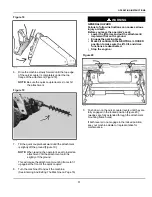
4.
At the same time, slowly lower the lift arms to drill
into the soil.
5.
When the auger bit has penetrated the ground about
610 mm (24 in), raise the attachment from the hole to
clean the dirt out of the hole. Repeat this procedure
until the desired hole depth is obtained.
Summary of Contents for Auger 75 DDH
Page 2: ......
Page 12: ...10 Figure 4 C221899a SAFETY AND TRAINING RESOURCES ...
Page 29: ......
Page 52: ...50 troubleshooting 29 W warranty 48 welding safety 7 ALPHABETICAL INDEX ...
Page 53: ......


