-9-
www.igmtools.com
Pic. 45
Head stock clamp lever.
The head stock clamp lever allows the head
stock to be released and moved to any position
on the lathe bed. It is located at the back of the
head stock.
6.7 Variable speed adjustment knob
Pic. 40
Pic. 41
Pic. 42
Pic. 43
Ensure that the bore of the head stock is clean.
The drive centre has a number 2 Morse Taper
that fits into the head stock. Push the centre
into the head stock bore firmly, and ensure that
it is securely located. To remove the centre,
push the rod into the back of the head stock,
and give it a sharp knock. This will remove the
drive centre.
Note
: Never leave the rod in the
head stock with the machine running.
6.5 Fitting the face plate
Reverse the removal procedure, described
earlier.
6.6 Lathe controls
Emergency stop button
The emergency stop button will lock in the OFF
position when fully depressed. To reset it, twist
clockwise and it will pop out.
Forward / Reverse switch
The forward / reverse switch selects the
direction of the rotation of the spindle. The
forward / reverse switch must only be used
once the spindle has come to a complete stop.
Start / Stop
The start / stop buttons start the motor and the
rotation of the spindle.
Speed display
The speed display shows the RPM of the
spindle.
Variable speed adjustment knob
The Variable speed adjustment knob adjusts
the spindle speed.
The Variable speed adjustment knob adjusts
the spindle speed. Turns clockwise to increase
the speed, turns counter-clockwise to decrease
the speed.
Fitting the remote controller
The remote controller can be fitted in either of
two positions, attached to the tail stock or
attached to the tailstock leg.
Fitting the remote controller to the tailstock
leg.
1. Fit the support plate to the bed by removing
the two clamp bolts and with the two clamp
screws secure the support plate.
2. Fit the remote controller with the clamping
supplied screws.
3. Ensure that the cable is clear of any
obstruction.
Fitting the remote controller to the tailstock.
1. Fit the support plate to the tailstock bracket
with the clamp screws supplied.
2. Fit the remote controller with the clamping
supplied screws.
3. Ensure that the cable is clear of any
obstruction.
Spindle
lock
Face plate
hole
spindle
lock
Drive centre removal shaft
drive centre
Emergency stop button
Start / Stop
Forward / reverse switch
Speed
display
Variable speed adjustment knob
Pic. 44
Pic. 46
Increase speed
Decrease speed
Head stock clamp lever
Summary of Contents for LAGUNA 2436
Page 2: ...2 www igmtools com...
Page 12: ...12 www igmtools com Electrical drawing Wiring diagram for control panel on headstock...
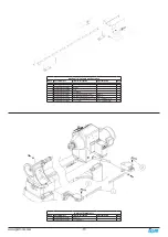
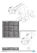
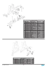
Page 13: ...13 www igmtools com Exploded view drawings and parts list Wiring diagram for remote control...
Page 14: ...14 www igmtools com...
Page 20: ...20 www igmtools com...
Page 21: ...21 www igmtools com...


