background image

-4-

www.igmtools.com

Tail stock viewed from the front

Pic. 7

Tool rest

The tool rest can be moved to any position on 

the lathe bed and locked to suit the job at hand.

The tool rest has a tall profile to allow the bowl 

turner to turn steep angles. The leading edge

is made from 6 mm hardened steel. 

Tool rest assembled to the bed

Pic. 8

Tool rest

Pic. 9

Electrical system

220V: The electrical control system (VFD) is 

housed at the back of the head stock, The VFD

converts single phase 220v to three phase. 

There is a speed readout at the front of the 

lathe with controls to fine adjust the rpm of 

the spindle. A power cord with 220V plug is 

provided.

Tail stock travel 

                               114 mm

Tail stock removal                          Self-ejecting

Tail stock taper 

                                    MT 2

Faceplate  

                                 76 mm

Bed material 

                                    Steel

Weight (net/ship)       

   242 kg / 255 kg

3.3 Noise emissions

Equivalent A-weighted Sound pressure level 

according to EN ISO 3746: 75.66 dB(A). 

Uncertainty, K in decibels: 4.0 dB (A) according 

to EN ISO 4871 The figure quoted is emission 

levels and are not necessarily safe working 

levels. Whilst there is a correlation between the 

emission and exposure levels, this cannot be 

used reliably to determine whether or not further 

precautions are required. Factors that influence 

the actual level of exposure of the workforce 

include characteristics of the work room, the 

other sources of noise, etc. i.e. the number of 

machines and other adjacent processes. Also 

the permissible exposure level can vary from 

country to country, This information, however, 

will enable the user of the machine to make a 

better evaluation of the hazard and risk.

Pic. 13

4. General safety


“WARNING“: For Your Own Safety Read 

Instruction Manual before Operating Lathe 


4.1 

Safety Rules

(a) Wear eye protection.

(b) Do not wear gloves, a necktie, or loose 

clothing.

(c) Tighten all locks before operating.

(d) Rotate work piece by hand before applying 

power.

(e) Rough out work piece before installing on 

faceplate.

(f) Do not mount split work piece or one 

containing a knot.

(g) Use lowest speed when starting new work 

piece.

• Keep guards in place and in working order. 

• Remove adjusting keys and wrenches. Form 

habit of checking to see that keys and adjusting 

wrenches are removed from tool before turning 

it on.

• Keep work area clean. Cluttered areas and 

benches invite accidents.

• Don‘t use in a dangerous environment. Don‘t 

use power tools in damp or wet locations, or 

expose them to rain. Keep work area well 

lighted.

VFD with cover open

Pic. 10

Power cord

Pic. 11

Tool storage

A tool storage bracket which can be mounted 

on either leg.

Tool storage bracket

Pic. 12

3.2 Technical data

Motor 

Induction,1725RPM, 3 HP 220V

Voltage 

220V, 60 Hz, 1 Ph.  

3 phase output

Recommended breaker size 

16 A, tripping 

characteristic C (16/1/C).

Swing over bed 

609 mm

Swing over banjo 

501 mm

Outboard swing max. 

965 mm

Distance between centres 

914 mm

Floor to spindle centre 

1130 mm

Floor to bed height 

826 mm

Dim. W x D x H 

1524 x 660 x 1327 mm

Tool rest 

305 mm

Speed range high: 

135 – 3500 rpm

Speed range low: 

50 – 1300 rpm

VFD 

DeltaS1 variable frequency drive 

Spindle 

1.25” x 8 tpi right hand thread

Spindle taper 

MT 2

Spindle lock 

Spring loaded

Spindle indexing 

14 / 36 / 48 with lock

Head stock and tail stock bore                 9,5 mm


Summary of Contents for LAGUNA 2436

Page 1: ...unatools com Distributor IGM n stroje a stroje s r o Ke Kopanin 560 252 67 Tuchom ice Czech Republic EU Phone 420 220 950 910 E mail sales igmtools com Website www igmtools com 2022 04 26 151 2436 LAG...

Page 2: ...2 www igmtools com...

Page 3: ...e tool rest and hand held cutting tools 3 1 Parts of the machine The lathe consists of a number of major parts which are discussed in this manual Take the time to read this section and become familiar...

Page 4: ...will enable the user of the machine to make a better evaluation of the hazard and risk Pic 13 4 General safety WARNING For Your Own Safety Read Instruction Manual before Operating Lathe 4 1 Safety Ru...

Page 5: ...he owner s manual for recommended accessories The use of improper accessories may cause risk of injury to persons Never stand on tool serious injury could occur if the tool is tipped or if the cutting...

Page 6: ...l capability of achieving 5 Lower the bed of the lathe onto 2 stacks of wood This will allow access to the underside of the bed Pic 22 5 2 Receiving the lathe Before you unpack your new machine you wi...

Page 7: ...semble the legs headstock tail stock tool storage and the tool rest to the bed of the machine Note It is recommended that the head stock tool rest and tail stock be removed from the bed of the lathe t...

Page 8: ...left hand thread Removal tool Pic 39 described procedure seek professional assistance Fit the 4 levelling feet to the lathe legs with the lock nut on the underside of the leg Once both legs have been...

Page 9: ...Stop The start stop buttons start the motor and the rotation of the spindle Speed display The speed display shows the RPM of the spindle Variable speed adjustment knob The Variable speed adjustment k...

Page 10: ...3 sets of indexing holes 14 36 48 The selection plunger is located at the end of the head stock To move between the 3 sets of holes loosen the clamp knobs and slide the indexing plunger assembly to al...

Page 11: ...pindle is extended or retracted 1 Loosen the clamp screw that is accessible from the top on the head stock 2 Tap the side of the headstock with a rubber mallet close to the base in the direction requi...

Page 12: ...12 www igmtools com Electrical drawing Wiring diagram for control panel on headstock...

Page 13: ...13 www igmtools com Exploded view drawings and parts list Wiring diagram for remote control...

Page 14: ...14 www igmtools com...

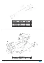
Page 15: ...191 C Ring R22 1 92 PLAREVO1836 192 Socket Head Cap Screw 1 4 20UNCx1 1 93 PLAREVO1836 193 Hex Cap Screw 3 8 16UNCx1 2 1 94 PLAREVO1836 194 Socket Head Button Screw M8x20 2 95 PLAREVO1836 195 Socket H...

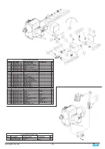
Page 16: ...Rubber Sleeve 1 11 PLAREVO1836 1145 Cap 1 12 MPAREVO1836 189 E Ring E15 4 13 PLAREVO1836 185 Key 6x6x30 1 14 PLAREVO1836 194 Socket Head Button Screw M8x20 1 15 PLAREVO1836 315 Socket Head Button Scr...

Page 17: ...3 Hinge 1 4 PLAREVO1836 404 Pin 2 5 PLAREVO1836 147 Stop Bolt 1 6 PLAREVO1836 406 Socket Head Cap Screw M6x12 4 7 PLAREVO1836 407 Phillips Flat Head Screw M5x12 5 8 PLAREVO1836 320 Socket Head Button...

Page 18: ...VO1836 811 L Type Fitting 1 12 PLAREVO1836 812 Air Flow Regulator 1 13 PLAREVO1836 813 Quick Release Fitting 1 14 PLAREVO1836 814 Pressure Vacuum Gauge 1 15 PLAREVO1836 815 Gauge Fitting 1 16 PLAREVO1...

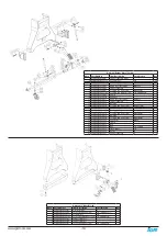
Page 19: ...PLAREVO1836 905 Nylon Insert Lock Nut M8x1 25 6 6 PLAREVO1836 906 Support Bracket 2 7 PLAREVO1836 907 Socket Head Cap Screw M8X45mm 2 8 PLAREVO1836 1146 Socket Head Button Screw 1 4 20UNCx3 8 8 9 PLAR...

Page 20: ...20 www igmtools com...

Page 21: ...21 www igmtools com...

Page 22: ...IGM n stroje a stroje s r o Ke kopanin 560 Tuchom ice 252 67 Czech Republic E U 420 220 950 910 www igm cz 2022 IGM n stroje a stroje s r o...

Reviews: