-11-
www.igmtools.com
removed they will cause rust. In general, we
recommend that you only use a Teflon-based
lubricant on the lathe. Regular oil attracts dust
and dirt. Teflon lubricant tends to dry and has
less of a tendency to accumulate dirt and saw
dust.
Periodically check that all nuts and bolts are
tight.
Drive belt
The drive belt should last for many years
(depending on the usage) but needs to be
inspected regularly for cracks, cuts and general
wear. If damage is found, replace the belt.
Bearings
All bearings are sealed for life and do not
require any maintenance. If a bearing becomes
faulty, replace it.
Rust
The lathe is made from steel and cast iron. All
none-painted surfaces will rust if not protected.
It is recommended that they be protected by
applying wax or a Teflon- based lubricant to
them.
Centre point alignment and slide
clearance adjustment
The centre point alignment and slide clearance
are adjusted at the factory and no adjustment
should be required. Should movement or wear
have taken place, the following adjustment
procedure should be conducted. Note: The
slide clearance of the headstock and the tail
stock must be checked and adjusted should it
be needed prior to adjusting the centre point
alignment.
Centre points aligned
Slide adjustment
Loosen the clamp handle on the tail stock and
check for side movement. If it is excessive,
insert an Allen key into the adjusting screw and
tighten.
Note:
By rotating the adjustment screw, it
moves into the adjusting slot which opens and
removes the excessive clearance between the
tail stock and the bed.
Note:
Only make very small adjustments and
then recheck the clearance. After adjustment
Centre points aligned the tail stock should be
slid along the bed to check for any area that it
binds in the bed slot. The same procedure as
above should be conducted on the head stock
should it be required.
Note:
It is very unlikely that the headstock will
require adjustment as it is not moved as often
as the tail stock, so has less tendency‘s for ware.
View under the tail stock
View under headstock
Center point alignment
The tail stock has two clamp screws that are
accessible from the top of the tail stock.
The clamp screws hold the slide plate to the tail
stock casting. There is clearance in the holes
that allows the tail stock to be moved in relation
to the slide plate. The headstock also has two
clamp screws, but one is accessible from under
the headstock.
By loosening the clamp screws the headstock
and tail stock can be moved and the centre
points aligned.
Note:
It is recommended that the head stock be
adjusted and not the tail stock. If the tail stock is
not adjusted parallel to the bed slide, the centre
point will not be in alignment when the spindle
is extended or retracted.
1. Loosen the clamp screw that is accessible
from the top on the head stock.
2. Tap the side of the headstock with a rubber
mallet close to the base in the direction
requiring adjustment and retighten the clamp
screw.
3. Recheck the centre point alignment and
repeat if required.
Note:
Never hit any part of the lathe that is cast
iron with a metal hammer or similar as it
will
break the casting.
8. Troubleshooting
Lathe will not start
1. Check that the start switch is in the correct
position.
2. Check that the electrical power cord is
plugged into the power outlet.
3. Check that the electrical supply is on (reset
the breaker).
4. With the power disconnected from the
machine, check that the wiring to the plug is
correct. Check that the rubber insulation is
stripped enough and is not causing a bad con-
nection. Check that all the screws are tight.
5. Emergency stop button engaged. Reset
emergency stop button. Twist and it will pop out.
The machine will not stop
This is a very rare occurrence as the machine is
designed to be fail-safe. If it should occur
and you cannot fix the fault, seek professional
assistance. The machine must be disconnected
from the power and never run until the fault has
been rectified.
1. The stop switch is faulty. Replace the stop
switch.
Motor tries to start but will not turn
1. With the power disconnected from the
machine, try to turn the spindle by hand. If
the spindle will not turn, check the reason for
jamming.
2. Capacitor faulty. Replace the capacitor.
3. Motor faulty. Replace the motor.
4. Power line overloaded. Correct overloaded
condition.
5. Low voltage. Correct low voltage condition.
Motor overheats
The motor is designed to run hot, but should it
overheat it has an internal thermal overload
protector that will shut it down until the motor
has cooled, and then it will reset automatically.
If the motor overheats, wait until it has cooled
and restart. If the motor shuts down consistently
check for the reason. Typical reasons are dull
cutting tools, the motor cooling fan being
clogged or faulty, the motor cooling fins are
clogged, overfeeding the job, and excessive
ambient temperature.
Squeaking noise
1. Check that the motor cooling fan is not con-
tacting the fan cover.
2. Check the bearings.
3. Check the drive belt is tensioned correctly.
Spindle slows down during a cut
1. Dull cutting tools. Replace the tool or have it
re-sharpened.
2. Feeding the wood too fast. Slow down the
feed rate.
3. Oil or dirt on the drive belt. Clean or replace
the drive belt.
4. Drive belt loose. Re-tension drive belt.
Machine vibrates
1. Machine not level on the floor. Re-level the
machine ensuring that it has no movement.
2. Damaged drive belt. Replace the belt.
3. Job is not balanced. Change to slower speed
and/ or balance the job.
4. Damaged pulley. Replace the pulley.
5. Worn spindle bearing. Replace the bearing.
Adjustment
slots
Clamp
screw
Adjusting
screw
Headstock
clamp
screw
Adjustment
slots
Summary of Contents for LAGUNA 2436
Page 2: ...2 www igmtools com...
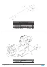
Page 12: ...12 www igmtools com Electrical drawing Wiring diagram for control panel on headstock...
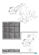
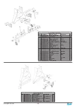
Page 13: ...13 www igmtools com Exploded view drawings and parts list Wiring diagram for remote control...
Page 14: ...14 www igmtools com...
Page 20: ...20 www igmtools com...
Page 21: ...21 www igmtools com...


